
Manufacturing Method Of Pneumatic Tire

Inactive Publication Date: 2008-11-27
TOYO TIRE & RUBBER CO LTD
View PDF8 Cites 5 Cited by
  • Summary
  • Abstract
  • Description
  • Claims
  • Application Information

AI Technical Summary

Benefits of technology

[0009]The present invention is made by taking the actual condition mentioned above into consideration, and an object of the present invention is to provide a manufacturing method of a pneumatic tire which can shorten a forming time so as to improve a production efficiency while securing a forming precision of a tire.
[0017]The present invention is to form the unvulcanized tire (green tire) by forming the annular rubber member in accordance with the first step as mentioned above, and attaching the annular rubber member to the carcass body in accordance with the second step as mentioned above. In accordance with the conventional manufacturing method, the injection molded rubber member is completely released from the forming mold, and is fed to the manufacturing line so as to be attached to the carcass body. On the contrary, in accordance with the present invention, since the rubber member is attached by moving the mold portion of the forming mold close to the carcass body in which the center portion is evaginated, it is possible to precisely and accurately position and attach the annular rubber member which is not vulcanized and has the low rigidity, and it is possible to shorten the forming time while securing the forming precision of the tire. Since the rubber member is released from the forming mold by moving the mold portion of the forming mold away from the carcass body, and has been already attached to the carcass body, the rubber member is prevented from getting out of shape.
[0019]In the present invention, it is preferable to attach the rubber member while deforming the carcass body in an evaginating manner, in the second step. Accordingly, it is possible to press an exposed side surface of the rubber member to a side portion of the carcass body, by utilizing an evaginating force of the carcass body, and it is possible to easily and suitably attach the rubber member.

Problems solved by technology

In the tire forming step as mentioned above, for example, if the side wall rubber is obtained by cutting an extrusion molding product at a predetermined length, there is a problem that a joint portion becomes locally thick on the basis of an overlapping or a close attaching between the end portions at a time of being formed as a cylindrical shape, thereby lowering a uniformity of a tire.
Further, there is a problem that a shape of the side wall rubber is not stabilized because the side wall rubber is pressed by the bladder at a time of winding up or a circumferential length of the side wall rubber is increased.
However, in accordance with this method, a forming time is elongated because a winding man hour of the rubber ribbon is increased, and there is a problem that a crack tends to be generated along an interface of the wound rubber ribbon.
However, since the annular rubber member which is not vulcanized and has a low rigidity is handled, it takes a long time to precisely position and attach, it is not sufficient in the light of securing the forming precision of the tire and shortening the forming time, and there is room for further improving these points.

Method used


Image

  • Manufacturing Method Of Pneumatic Tire
  • Manufacturing Method Of Pneumatic Tire
  • Manufacturing Method Of Pneumatic Tire

Examples


Embodiment Construction

[0027]An embodiment of the present invention will be explained with reference to the drawings.

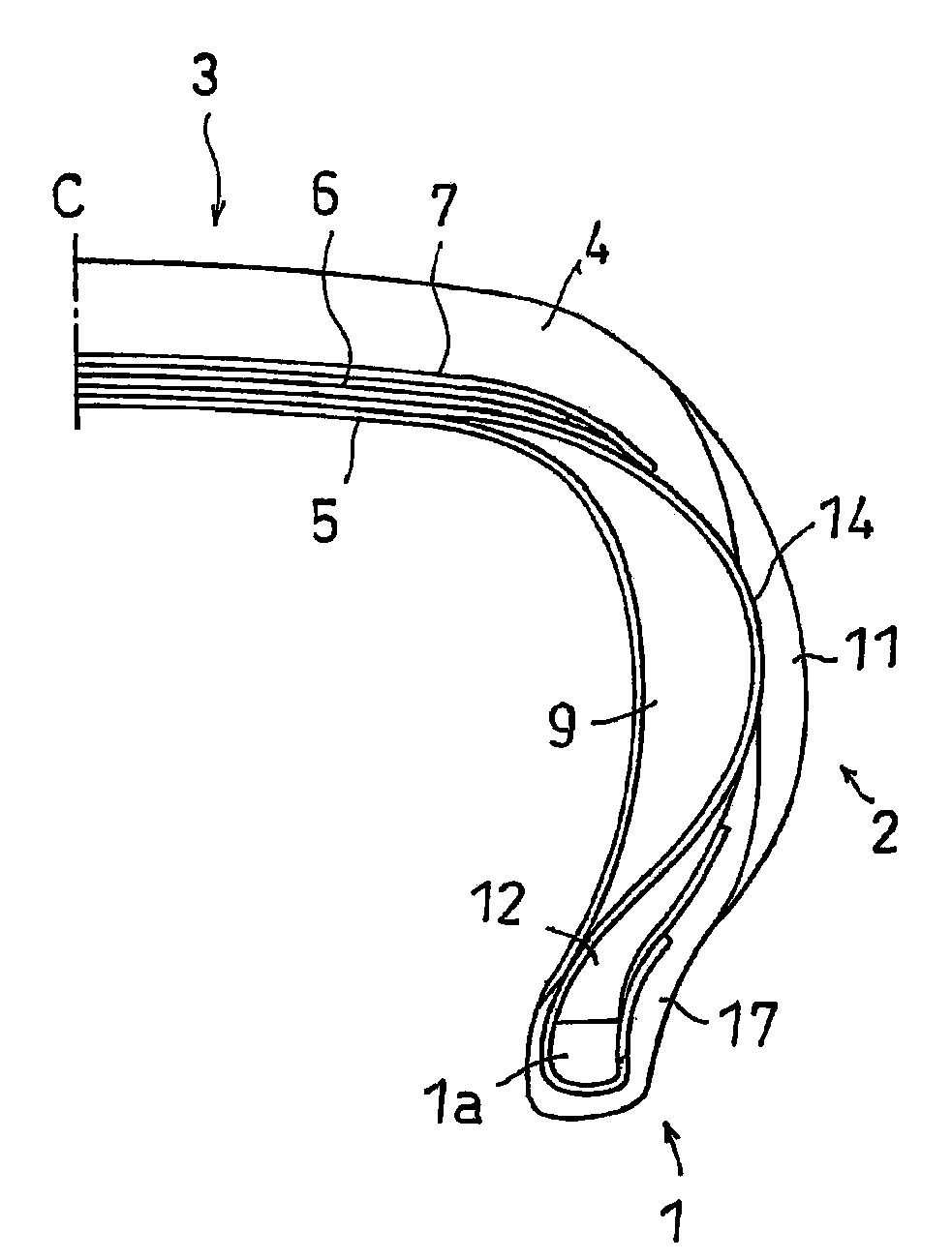
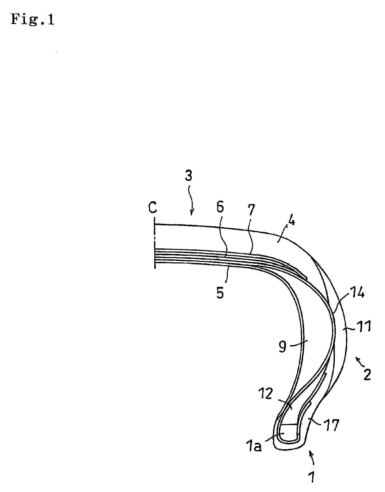
[0028]FIG. 1 is a half cross sectional view of a tire meridian line showing one example of a pneumatic tire manufactured by the present invention. The pneumatic tire comprises a pair of bead portions 1, sidewall portions 2 extending from respective bead portions 1 radially outward of the tire, and a tread portion 3 provided between the sidewall portions 2. In the bead portion 1, there are arranged an annular bead 1a constituted by a convergence body of a steel wire or the like, and a bead filler 12 formed as a triangular cross sectional shape in an outer side in a tire diametrical direction of the bead 1a, and an end portion of a carcass ply 14 is wound up to an outer side in such a manner as to pinch them.

[0029]An inner liner rubber 5 for retaining a pneumatic pressure is arranged in an inner peripheral side of the carcass ply 14. Further, a rim strip rubber 17 is arranged in an outer peri...


PUM


Abstract

An annular side wall rubber is injection molded, a forming mold is mold released while retaining the side wall rubber in an unvulcanized state, and a side surface of the side wall rubber is exposed annularly. Further, a lower mold of the forming mold is moved close to a carcass body in which a center portion is evaginated to an outer side in a diametrical direction, on a forming drum, and the side surface of the side wall rubber is attached to a side portion of the carcass body. Thereafter, the side wall rubber is released from the forming mold by moving the lower mold away from the carcass body.

Description

BACKGROUND OF THE INVENTION[0001]1. Technical Field[0002]The present invention relates to a manufacturing method of a pneumatic tire provided with a step of forming an unvulcanized tire by attaching a rubber member to a carcass body having a bead portion.[0003]2. Background Art[0004]A description will be simply given of one example of a conventional tire forming step with reference to FIG. 6. First, as shown in FIG. 6(a), an inner liner rubber 45, a side wall rubber 41, a carcass ply 44 and the like are wound around a forming drum 47 so as to be formed as a cylindrical shape, and an annular bead 42 and a bead filler 43 are outward inserted to both sides in a width direction of the carcass ply 44. Further, a cylindrical tread member 46 obtained by integrating a tread rubber and a belt is arranged in an outer peripheral side of a center portion of the carcass ply 44. The tread member 46 is manufactured in the other step, and is supported by a transfer ring (not shown).[0005]Next, as s...

Claims


Application Information

Patent Timeline
IPC IPC(8): B29D30/08
CPCB29D30/72B29D2030/201B29D2030/724
Inventor SEGAWA, MASAHIRO
Owner TOYO TIRE & RUBBER CO LTD
Features
  • Generate Ideas
  • Intellectual Property
  • Life Sciences
  • Materials
  • Tech Scout
  • Unparalleled Data Quality
  • Higher Quality Content
  • 60% Fewer Hallucinations
Learn More