Conical Scanning Antenna System Using Nutation Method

a scanning antenna and nutation method technology, applied in the direction of antennas, electrical equipment, etc., can solve the problem of asymmetry of tracking beams

Inactive Publication Date: 2008-11-27
ELECTRONICS & TELECOMM RES INST
View PDF4 Cites 7 Cited by
  • Summary
  • Abstract
  • Description
  • Claims
  • Application Information

AI Technical Summary

Benefits of technology

[0011]A conical scanning antenna system according to the present invention performs a satellite track

Problems solved by technology

Therefore, the tracking method using the rotation of the sub-reflector may caus

Method used


Image

  • Conical Scanning Antenna System Using Nutation Method
  • Conical Scanning Antenna System Using Nutation Method
  • Conical Scanning Antenna System Using Nutation Method

Examples


Embodiment Construction

[0019]Other objects and aspects of the invention will become apparent from the following description of the embodiments with reference to the accompanying drawings, which is set forth hereinafter.

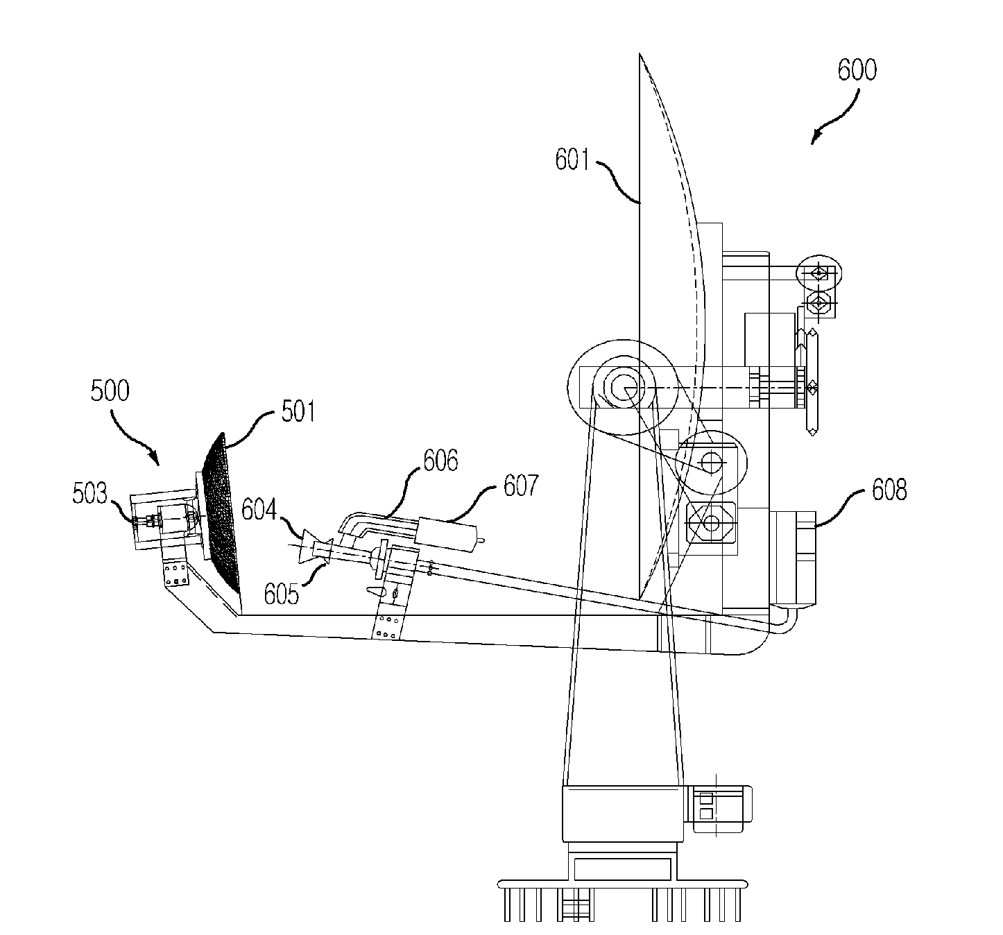
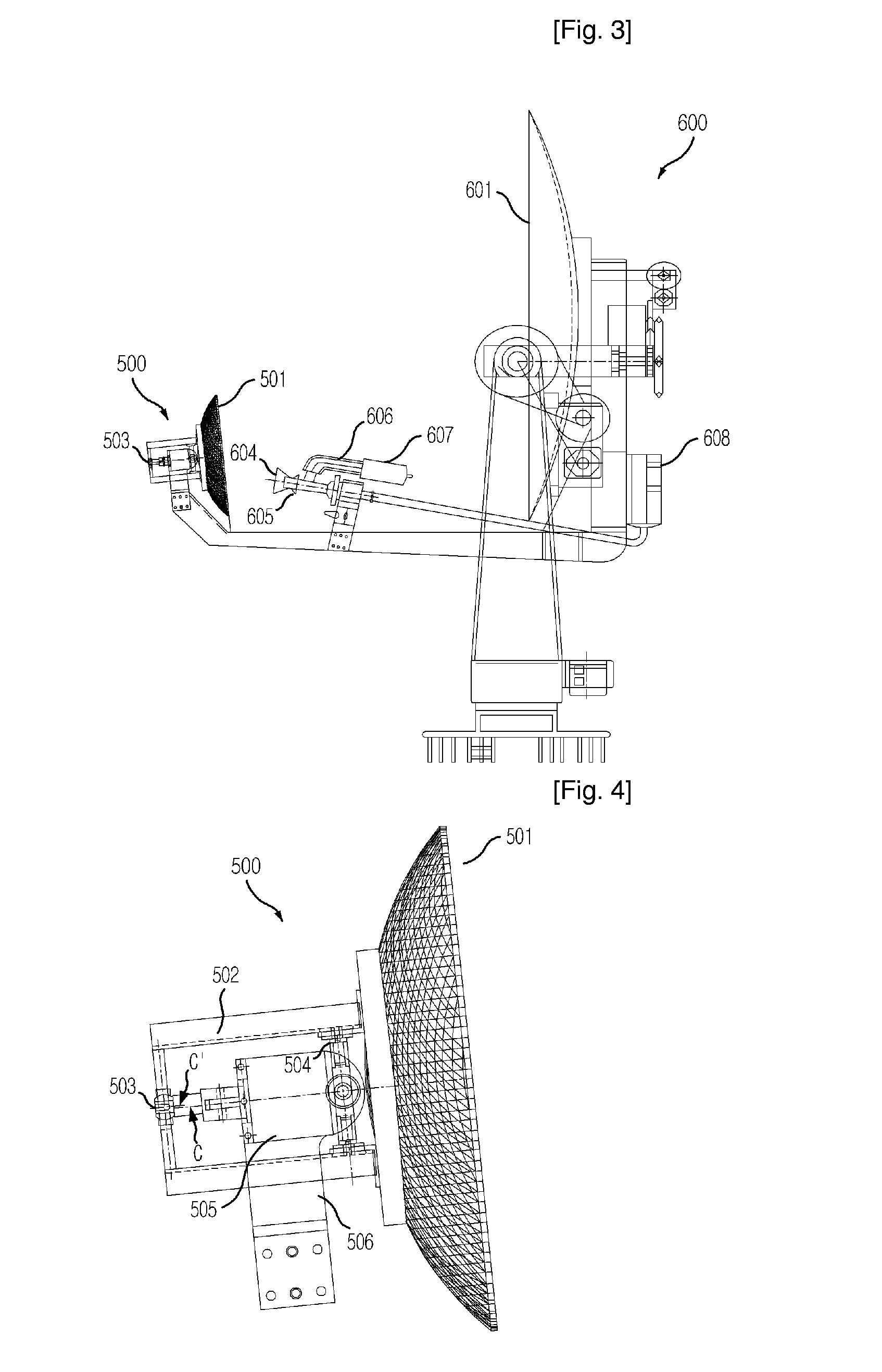
[0020]FIG. 3 shows a conical scanning antenna system using a nutation method in accordance with an embodiment of the present invention, and FIG. 4 is a view showing a sub-reflector of FIG. 3.

[0021]Referring to FIGS. 3 and 4, the conical scanning antenna system includes a main reflecting unit 600, a sub reflecting unit 500 and a feeding horn 604 which doubly reflects electromagnetic wave inputted and radiated by the main reflecting unit and the sub-reflecting unit and inputs and outputs the electromagnetic wave by electrically steering beams. The main reflecting unit 600 has a parabola shaped main reflector 601 with a circular contour line.

[0022]As shown in FIG. 4, the sub reflecting unit 500 is disposed apart from the main reflecting unit by a predetermined distance and performing a conical...


PUM


Abstract

Provided is a conical scanning antenna system using a nutation method. The conical scanning antenna system includes: a main reflecting unit; a sub-reflecting unit which is disposed apart from the main reflecting unit by a predetermined distance and performing a conical scanning tracking by using the nutation method; and a feeding horn which doubly reflects electromagnetic wave inputted and radiated by the main reflecting unit and the sub-reflecting unit and inputs and outputs the electromagnetic wave by electrically steering beams.

Description

TECHNICAL FIELD [0001]The present invention relates to a conical scanning antenna system using a nutation method; and more particularly to a conical scanning antenna system using a nutation method for effectively tracking a satellite by using a nutation method of a sub-reflector in an offset dual reflector antenna structure.BACKGROUND ART[0002]Generally, tracking algorithms for the satellite communication is classified into a closed loop method and an open loop method. The closed loop method is further classified into a lobing method and a mono-pulse method.[0003]The closed loop method is designed to control the antenna in a predicted orbit direction by processing satellite orbit forecasting data, standard time data, and antenna digital angle data using a computer. Therefore, the tracking performance of the antenna depends on the accuracy of the data. The lobbing method is designed to control the orientation of the antenna by detecting a coming direction of a bicorn wave by moving a...

Claims


Application Information

Patent Timeline
IPC IPC(8): H01Q3/12
CPCH01Q19/132H01Q3/10H01Q15/147H01Q15/16
Inventor YUN, JAE-SEUNGEOM, SOON-YOUNGJUNG, YOUNG-BAESON, SEONG-HOJEON, SOON-IK
Owner ELECTRONICS & TELECOMM RES INST
Why Eureka
Try Eureka