Liquid diffuser device for irrigation systems

a technology of liquid diffuser and irrigation system, which is applied in watering devices, horticulture, agriculture, etc., can solve the problems of high cost, time-consuming, and complex construction and assembly of the device, and achieve the effect of high efficiency and relatively cost-effectiv

Active Publication Date: 2016-12-06
KOMET AUSTRIA GMBH
View PDF9 Cites 9 Cited by
  • Summary
  • Abstract
  • Description
  • Claims
  • Application Information

AI Technical Summary

Benefits of technology

[0017]The object of the present invention is to overcome the above drawbacks, by providing a liquid diffuser device for irrigation systems that is highly efficient and relatively cost-effective.
[0018]A particular object of the present invention is to provide a liquid diffuser device for irrigation systems that has a simple structure.
[0019]Another object of the present invention is to provide a liquid diffuser device for irrigation systems that can be assembled in a remarkably short time.

Problems solved by technology

A first drawback of this arrangement is that its construction and assembly are rather complex and it has a relatively high cost.
This is because the second sphere must be manually inserted into the corresponding concave seat formed in the bottom surface of the stem, which is a time consuming operation, requiring remarkable manual dexterity of the assembly operator.
A further drawback of this known arrangement is that the provision of the intermediate member only partially reduces stem wear, and the resulting efficiency loss in the device.
Indeed, the nutation of the plate causes the side wall of the concave seat to wear, and may generate oscillatory vibrations of the plate, with the risk of causing the device to break or blocking the movement of the stem, which will prevent uniform distribution of the liquid jet on the soil portion to be irrigated.
Also, a further drawback of this solution is that, due to the wear of the seat, the diffuser member is required to be periodically replaced, which will increase the maintenance costs of the system.
Furthermore, during periodic maintenance of the diffuser device, the operation of the system is stopped, and the soil remains unirrigated for a given time, which will reduce the growth of crops or irremediably cause their destruction.

Method used


Image

  • Liquid diffuser device for irrigation systems
  • Liquid diffuser device for irrigation systems
  • Liquid diffuser device for irrigation systems

Examples


Embodiment Construction

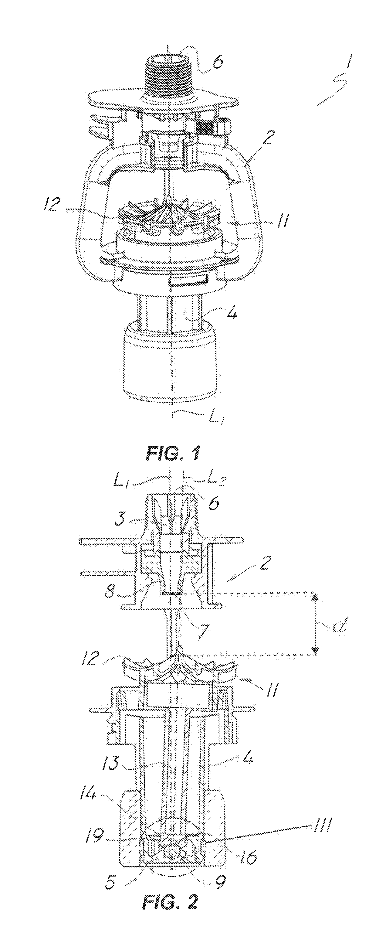
[0039]FIG. 1 shows a diffuser device for irrigation systems according to the invention, generally designated with numeral 1, which is designed for distribution of an irrigation liquid, generally water, over a soil to be irrigated.

[0040]Particularly, the diffuser may be connected to a water supply conduit via a drop line to form “center pivot” irrigation systems or the like.

[0041]As better shown in the figures, the diffuser device comprises a support structure 2 defining a first longitudinal axis L1 with an upper passageway 3 for a liquid jet and a lower tubular body 4 having a substantially transverse bottom wall 5.

[0042]As is known in the art, the support structure 2 may be connected to the irrigation system via the inlet 6 of the upper passageway 3.

[0043]Furthermore, a nozzle 8 may be fixedly or removably fitted at the outlet 7 of the upper passageway, for directing the liquid jet in a longitudinal direction, generally downwards.

[0044]As best shown in FIG. 2, the device is equippe...


PUM


Abstract

A liquid diffuser device for irrigation systems includes a support structure defining a first longitudinal axis with an upper passageway for a liquid jet and a lower tubular body having a bottom wall, a spherical member associated therewith having an outer surface with a predetermined average radius of curvature, a liquid jet deflecting member having an upper plate and a lower stem designed to be introduced into the tubular body and defining a second longitudinal axis. The stem interacts with the outer surface of the spherical member, to allow rotation of the stem relative to the body and nutation of the second axis relative to the first axis. The bottom surface is concave to define with the spherical member a relatively broad and substantially uniform contact surface, to reduce the local specific pressure, thereby decreasing friction, wear and vibrations on the stem and the spherical member during operation.

Description

FIELD OF THE INVENTION[0001]The present invention generally finds application in the field of irrigation systems for agricultural and industrial applications, and particularly relates to a liquid diffuser device for irrigation systems.BACKGROUND ART[0002]Some prior art agricultural and / or industrial irrigation systems comprise an irrigation liquid supply conduit, connected to a plurality of drop lines, each having a diffuser device for uniformly distributing a liquid jet to an underlying soil portion to be irrigated.[0003]A diffuser device typically comprises a main body with a tubular passage having one end connected to the drop line and the opposite end having a nozzle for delivery of a downward liquid jet.[0004]Furthermore, the device comprises a deflector member for obstructing and radially deflecting the liquid jet that flows out of the tubular passageway, for uniform distribution thereof over the soil portion to be irrigated.[0005]The deflector member generally comprises a ste...

Claims


Application Information

Patent Timeline
Patent Type & Authority Patents(United States)
IPC IPC(8): A01G25/02B05B3/04B05B3/00B05B1/26
CPCB05B1/265A01G25/02B05B3/008B05B3/0486
Inventor DRECHSEL
Owner KOMET AUSTRIA GMBH
Why Eureka
Try Eureka