
Lockable door assembly of an electronic device

a technology of electronic devices and lockable doors, which is applied in the direction of electrical apparatus construction details, carpet fasteners, instruments, etc., can solve the problems of no relevant mechanism and complicated lockable door assembly in the prior art, and achieve the effect of reducing the number of parts

Active Publication Date: 2008-11-27
GETAC TECH CORP
View PDF16 Cites 28 Cited by
  • Summary
  • Abstract
  • Description
  • Claims
  • Application Information

AI Technical Summary

Benefits of technology

[0007]The lockable door assembly in the prior art is complicated in the case of having large number of parts, and has no relevant mechanisms to avoid being opened accidentally. The object of the present invention is directed to provide a lockable door assembly that has reduced number of parts and can provide a double secure mechanism having a multi-locking function.
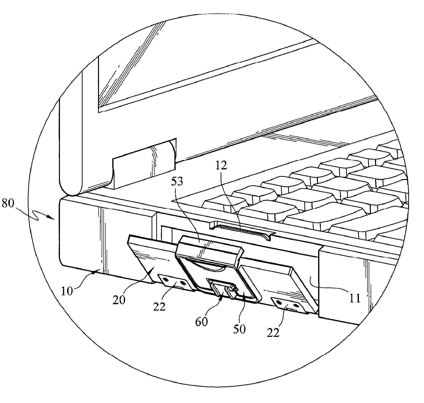
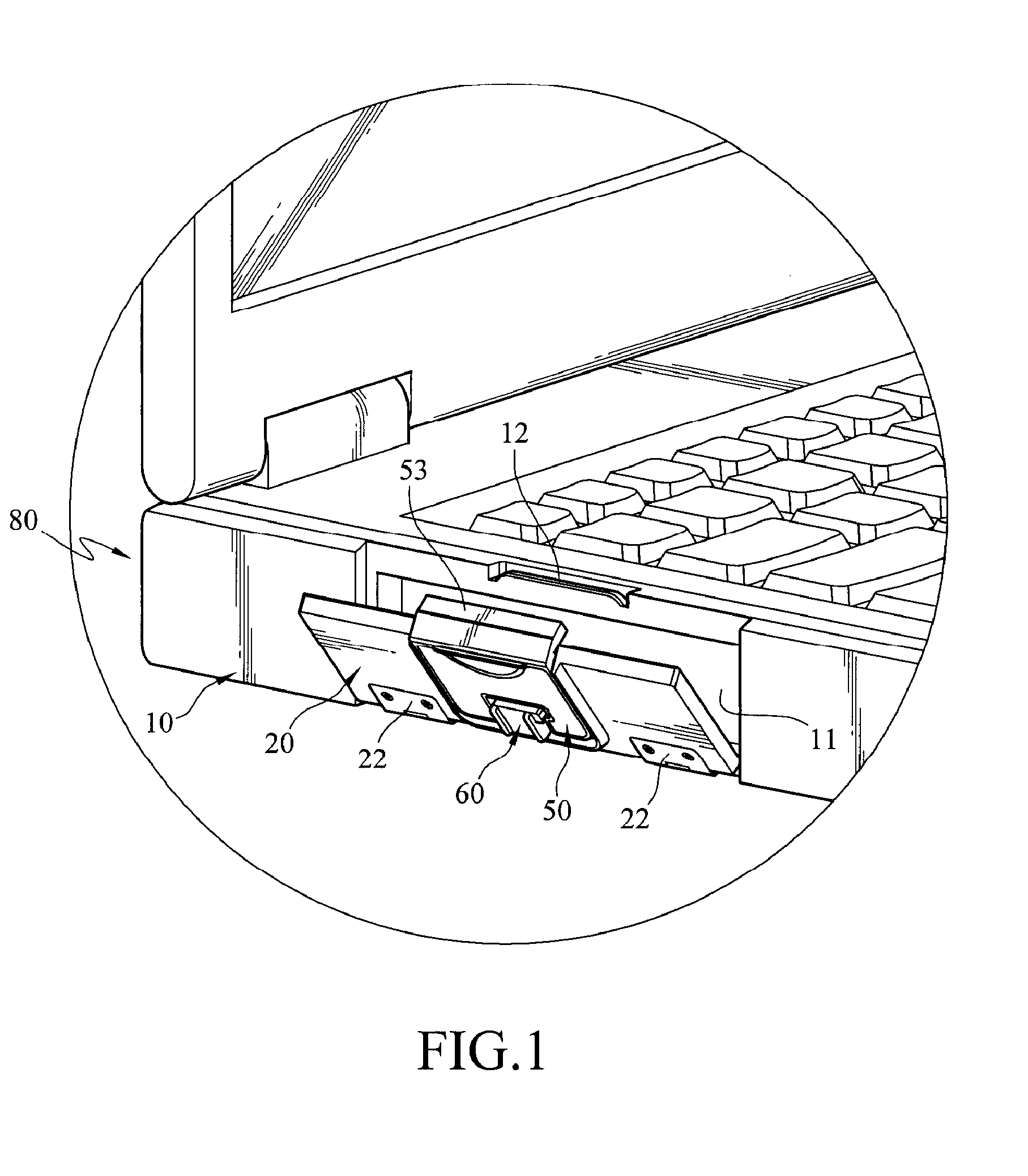
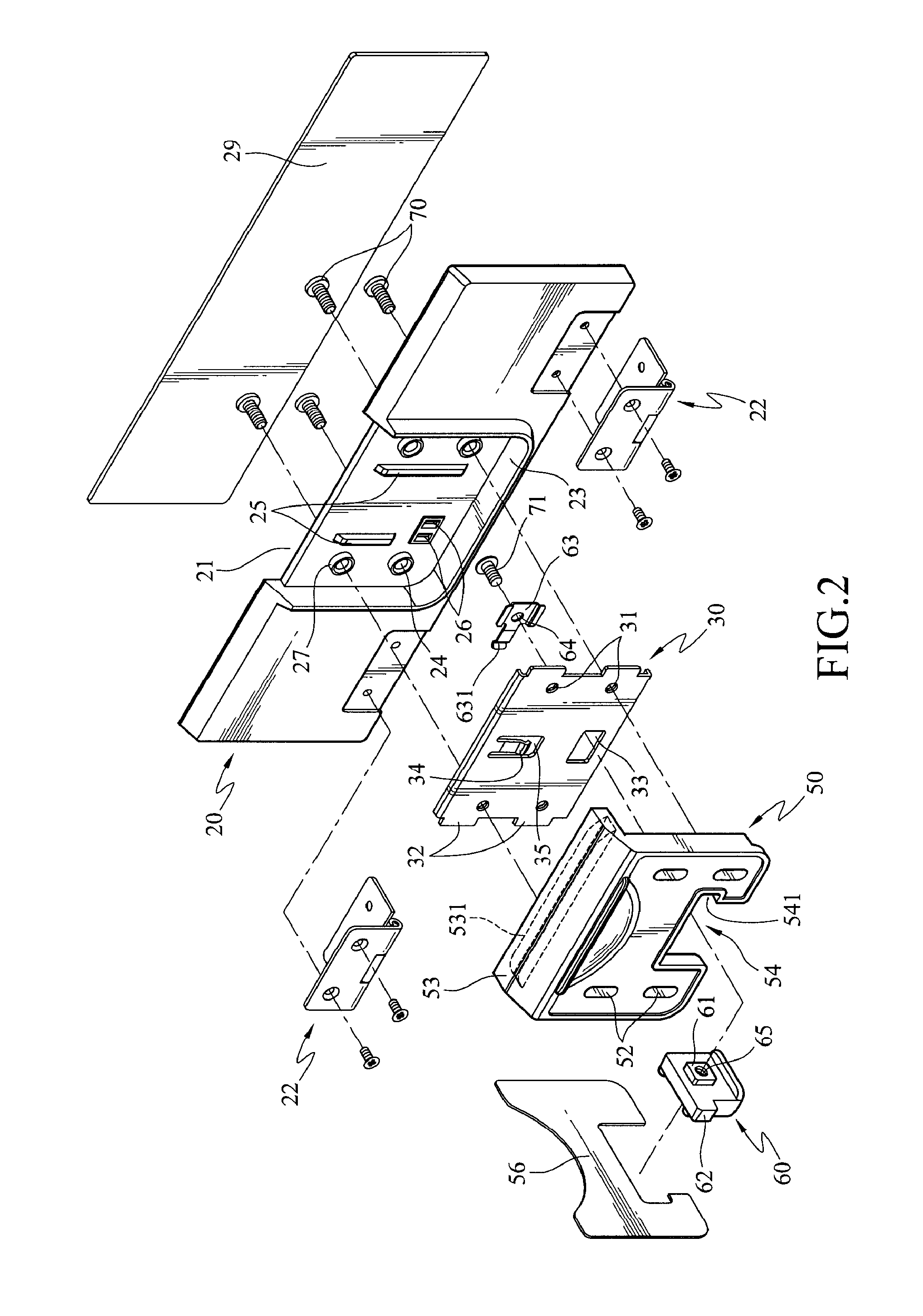
[0008]In order to achieve the aforementioned object, a lockable door assembly of the present invention is provided for covering and sealing an opening of a housing of an electronic device, wherein the housing has a rib formed thereon adjacent to the opening. The lockable assembly includes a door, a fixing member, a first sliding member, and at least one second sliding member. The door is pivoted to the housing for covering the opening, and the fixing member is fixed on the door. The first sliding member is movably disposed on the fixing member, and slides between a first position and a second position relative to the door. The first sliding member has a latching portion and at least one nick. The latching portion is engaged with the rib adjacent to the opening at the first position, so as to stop the door from rotating relative to the housing. The second sliding member is movably disposed on the fixing member, and the sliding paths of the second sliding member and the first sliding member are intersected on the same plane. The second sliding member is used for being inserted into the nick of the first sliding member to prevent the first sliding member departing from the first position, such that the latching portion of the first sliding member remains being engaged with the rib, thereby prevent the door from be released from the opening.
[0009]The advantages of the present invention lie in that the lockable door assembly has reduced number of parts and a simplified structure, so as to effectively enhancing structure strength and structure durability. And sliding paths of the first sliding member and the second sliding member slide are intersected on the same plane, thus not only reducing the thickness of the lockable door assembly, but also providing a double secure mechanism, thereby preventing the door from being opened due to the first sliding member being accidentally moved.

Problems solved by technology

The lockable door assembly in the prior art is complicated in the case of having large number of parts, and has no relevant mechanisms to avoid being opened accidentally.

Method used


Image

  • Lockable door assembly of an electronic device
  • Lockable door assembly of an electronic device
  • Lockable door assembly of an electronic device

Examples


first embodiment

[0032]Referring to FIGS. 2, 3, and 4, the fixing member 30 is a plate with an irregular edge and includes a plurality of bolt hole 31, a plurality of lobes 32, a sliding slot 33, a abutting sheet 34, and a cutting slot 35. The bolt holes 31 are formed in the fixing member 30 and communicate two side surface of the fixing member 30, and the positions and number of the bolt holes 31 are corresponding to those of the fixing holes 24 formed in the door 20. Each of the fixing holes 24 is provided for a bolting member 70 to pass through and to be screwed into the corresponding bolt hole 31, so as to fix the fixing member 30 to the inner region surrounded by the U-shaped flange 23 on the door 20. Furthermore, the front end of the bolting member 70 protrudes from one side of the fixing member 30. The lobes 32 are formed at opposite edges of the fixing member 30 and protrude outward from the edge of the fixing member 30, and are disposed symmetrically with respect to a central line of the fi...

second embodiment

[0043]Therefore, if the user intends to move the first sliding member 50 from the first position to the second position (i.e., before releasing the first securen mechanism), each of the second sliding members 90 must be moved firstly to withdraw from the nicks 512 of the first sliding member 50, and then the first secure mechanism may be released to open the door 20. In the second embodiment, the third and fourth secure mechanisms provided by the lockable door assembly may prevent the door 20 from being mistakenly opened if the second secure mechanism is released accidentally.

[0044]The lockable door assembly of the present invention has reduced number of parts and a simplified structure, thereby effectively enhancing structure strength and structure durability. The first sliding member 50 and the second sliding member 60 slide on the same plane, thus not only reducing the thickness of the lockable door assembly, but also providing a double secure mechanism that prevents the door 20 ...


PUM


Abstract

A lockable door assembly of an electronic device is used to cover and seal an opening of a housing of the electronic device. The lockable door assembly includes a door, a first sliding member, and a second sliding member. The door is pivoted to the housing to cover the opening. The first sliding member is movably disposed on the door for being engaged with a rib formed on the housing, so as to stop the door from rotating. The second sliding member is movably disposed on the door, and the sliding paths of the second sliding member and the first sliding member are intersected. The second sliding member is used for being inserted into a nick of the first sliding member to prevent the first sliding member from moving, thereby a double secure mechanism is achieved and the thickness of the lockable door is reduced.

Description

BACKGROUND OF THE INVENTION[0001]1. Field of Invention[0002]The present invention relates to a lockable door assembly of a housing, and more particularly to a lockable door assembly that has fine structure durability and provides multi-locking mechanisms.[0003]2. Related Art[0004]With rapid development of computers, laptops or portable computers which are quite convenient to be carried have gradually become the mainstream products in the market instead of desktop computers. However, in the early days, business or home laptops or portable computers have no space for future upgrade like desktop computers in consideration of manufacturing, costs, and so on, so that consumers cannot add some peripheral hardware devices such as hard disk drives and optical disk drives at will. Hence, in order to provide space for future upgrade, laptops or portable computers of certain types that allow users to install or replace hardware devices freely have developed in this industry.[0005]A laptop or p...

Claims


Application Information

Patent Timeline
Patent Type & Authority Applications(United States)
IPC IPC(8): H05K7/16
CPCG06F1/182Y10S292/11Y10S292/63G06F1/1658Y10T292/1028Y10T292/1023Y10T292/096Y10T292/1022
Inventor SHENG, YEN-LONG
Owner GETAC TECH CORP
Learn More