Optical link monitoring system and method for passive optical network

Inactive Publication Date: 2008-11-27
INVENTEC CORP
View PDF2 Cites 29 Cited by
  • Summary
  • Abstract
  • Description
  • Claims
  • Application Information

AI Technical Summary

Benefits of technology

[0007]It is an object of the present invention to provide an optical link monitoring method for

Problems solved by technology

Besides, the transmission quality might get deteriorated because the optical cable is affected by the environment, such as compressed or impacted under construction, or bent by gravity.
Such deterioration process is usually too slow to become aware instantly and will cause

Method used


Image

  • Optical link monitoring system and method for passive optical network
  • Optical link monitoring system and method for passive optical network
  • Optical link monitoring system and method for passive optical network

Examples


Example

[0019]Some embodiments of the invention will now be described in greater detail. Nevertheless, it should be noted that the present invention can be practiced in a wide range of other embodiments besides those explicitly described, and the scope of the present invention is expressly not limited except as specified in the accompanying claims.

[0020]Note that, the components of the different elements are not shown to scale. Some dimensions of the related components are exaggerated to provide a more clear description and comprehension of the present invention.

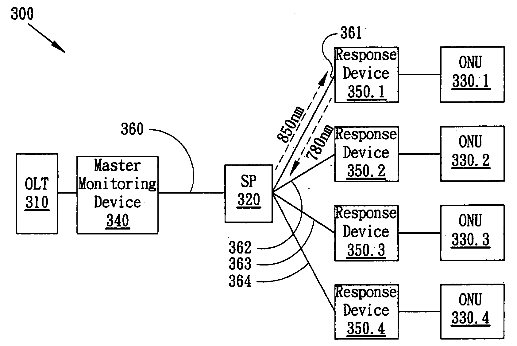
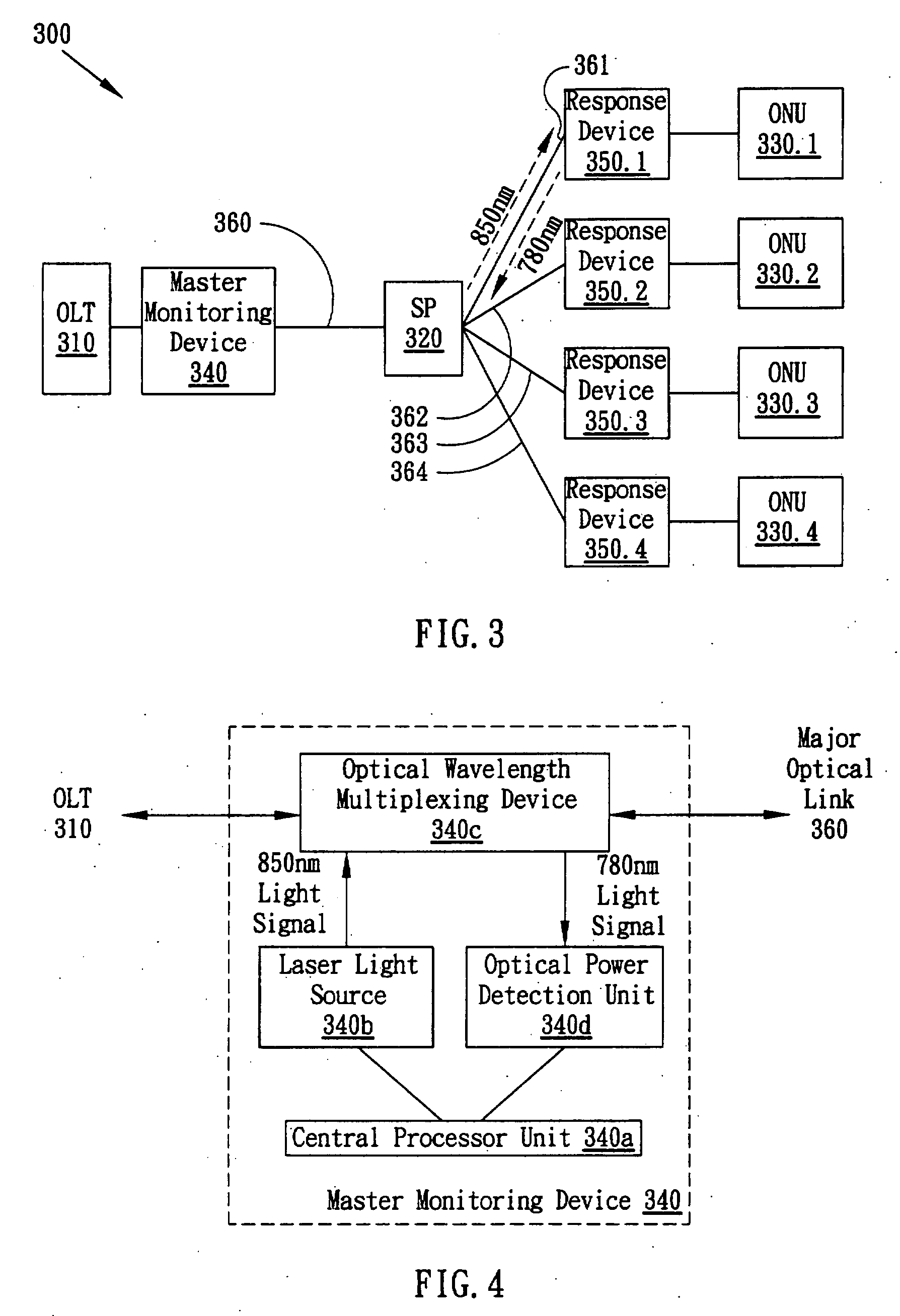
[0021]FIG. 3 shows a schematic diagram of the passive optical network system 300 with the optical link monitoring capability according to an embodiment of the present invention, including an optical line terminal 310, a master monitoring device 340, a splitter 320, response devices 350.1-350.4 (which may be hereafter alternatively referred to as response devices 350) and optical network units 330.1-330.4. In contrast with the tradit...


PUM


Abstract

The present invention provides an optical link monitoring system for the passive optical network. The system includes a master monitoring device connected to an optical line terminal and a plurality of response devices respectively connected to a plurality of optical network units. Through time division multiplexing technology, the master monitoring device broadcasts a predetermined instruction to the response devices to answer back predetermined optical signals in turn. The master monitoring device also measures the optical power of the returned predetermined optical signals and diagnoses the status of the optical links. The present invention also provides an optical link monitoring method.

Description

BACKGROUND OF THE INVENTION[0001]1. Field of the Invention[0002]The present invention is related to the monitoring technology for Passive Optical Network (PON), especially to a method for monitoring the status of optical links through the TDM (Time Division Multiplexing) technology to get the responses sequentially from the Optical Network Units (ONU).[0003]2. Description of the Prior Art[0004]With the features of big capacity, high reliability and long transmission distance, the optical fiber becomes the backbone of the telephony communication links. The service transmitting the data to clients directly by the optical fiber will be more widespread. Typical services include, for example, fiber to the cabinet (FTTCab), Fiber To The Curb (FTTC), Fiber To The Building (FTTB) and Fiber To The Home (FTTH) which are services generally referred to as FTTx. Based on the structure with no power sources, Passive Optical Network (PON) has the great chance to prevail over other optical linking ...

Claims


Application Information

Patent Timeline
IPC IPC(8): H04B10/20H04J14/00
CPCH04B10/0773H04J14/0226H04J14/0227H04J14/0282H04J14/0247H04J14/0252
Inventor LU, TIEN-HSIANG
Owner INVENTEC CORP
Why Eureka
Try Eureka