Input Device Having Tactile Function, Information Input Method, and Electronic Device

Active Publication Date: 2008-12-04
SONY CORP
View PDF7 Cites 40 Cited by
  • Summary
  • Abstract
  • Description
  • Claims
  • Application Information

AI Technical Summary

Benefits of technology

[0011]For example, the computation means computes a vibration pattern of the input detection plane to generate vibrations from its low frequency and small amplitude to its high frequency and large amplitude, as the operation body goes away from a position where it has touched the inp

Problems solved by technology

In this connection, in the case of configuring a haptic function-provided input device by combining a plurality of vibrators and input means so that a haptic sense may be obtained through an operation to straightly touch its input operation surface, it is predicted that mere combination of the mec

Method used


Image

  • Input Device Having Tactile Function, Information Input Method, and Electronic Device
  • Input Device Having Tactile Function, Information Input Method, and Electronic Device
  • Input Device Having Tactile Function, Information Input Method, and Electronic Device

Examples


first embodiment

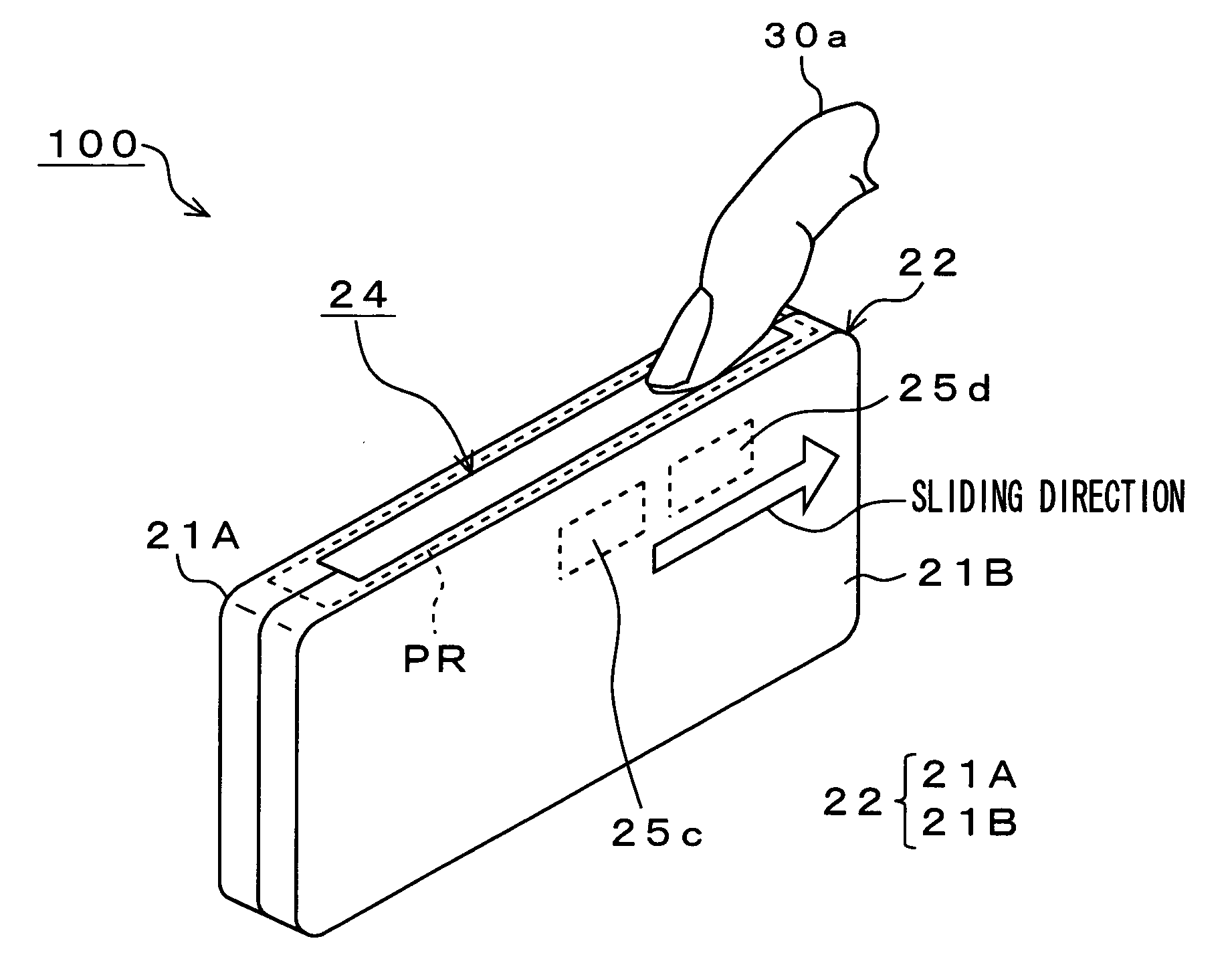
[0066]In the first embodiment, vibration means for vibrating an input detection plane in accordance with a vibration pattern computed based on a touch position and a sliding speed of an operation body on this input detection plane is provided, thereby enabling to be generated plural kinds of vibrations which have different periods of vibration time (frequency, amplitude, and the number of times) for each operator and which correspond to a sliding speed or a lapse of sliding time of the finger etc. of the operator, which is the operation body.

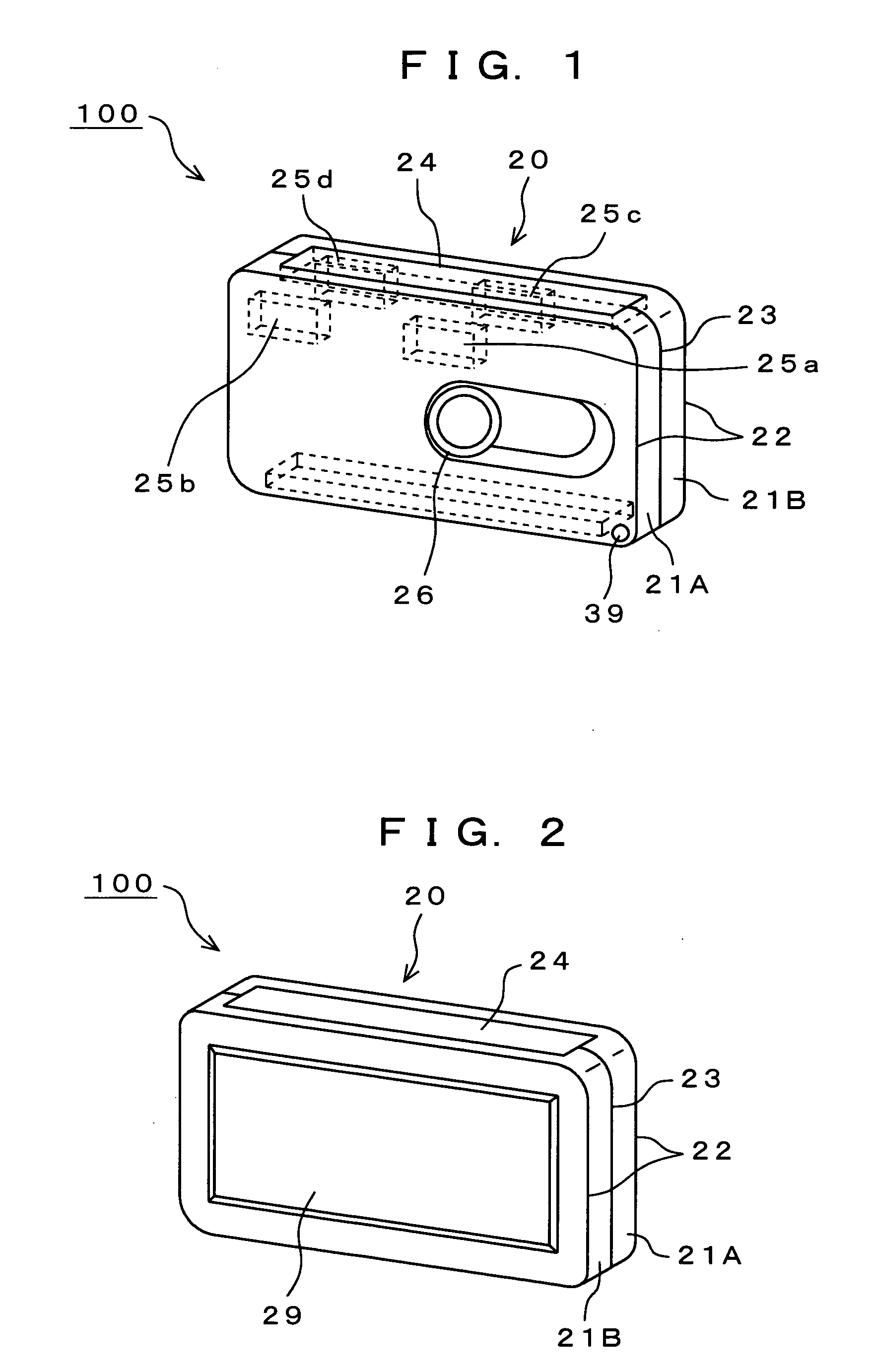
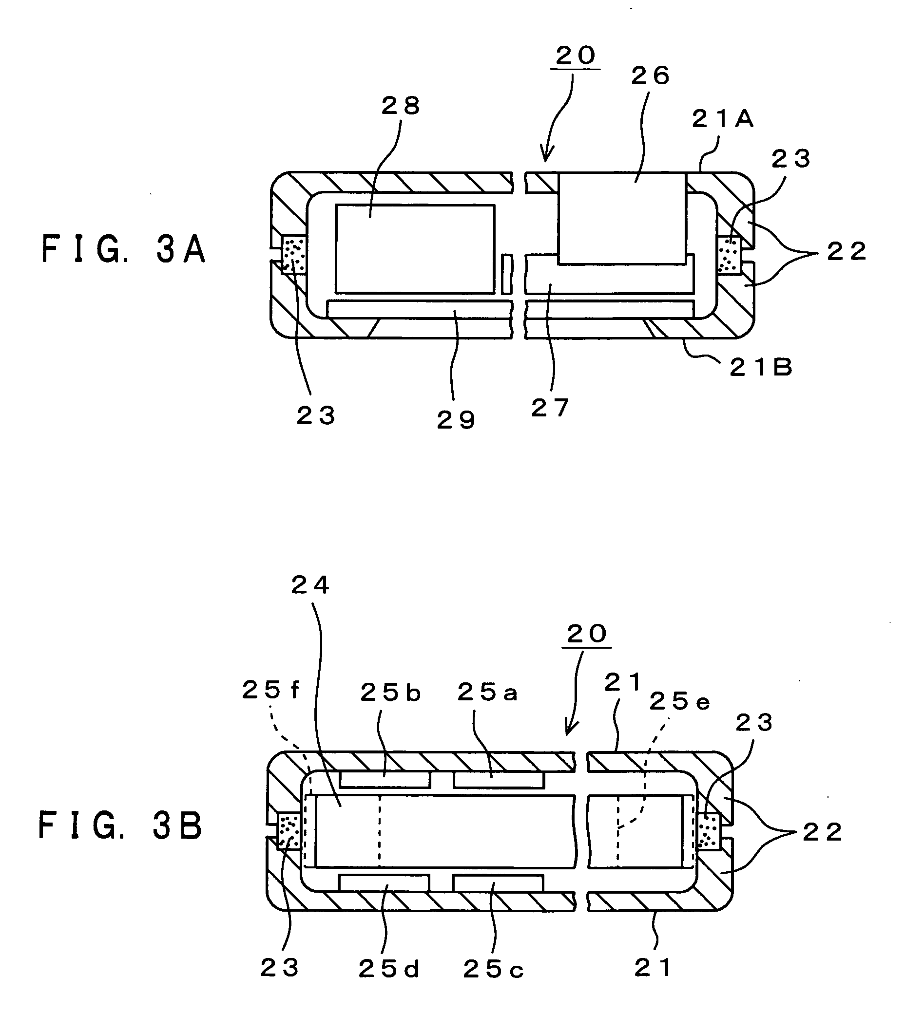
[0067]A digital camera 100 shown in FIG. 1 is one example of electronic devices to which a haptic function-provided input device related to the present invention is applied. This digital camera 100 has a camera body 20. The camera body 20 is constituted of a chassis 22. The chassis 22 is assembled by causing a front case 21A and a rear case 21B that are roughly box-shaped to abut against each other with a roughly square-shaped shock absorber 23 ...

second embodiment

[0174]The following will describe an example of a haptic function-provided input mechanism of a digital camera 200 as the second embodiment. In the second embodiment, input information is controlled variably based on distance information Lx on a distance from a point where the finger 30a of an operator touches an input detection plane PR to a point where its sliding stops.

[0175]In contrast to the first embodiment, according to the haptic function-provided input mechanism of the digital camera 200 shown in FIG. 16, below an input detection section 24, actuators A and B are provided. The input detection section 24 is arranged to bridge between the actuators A and B in such a configuration that these actuators A and B serve as bridge girders. As the actuators A and B, the actuators 25e and 25f described with the first embodiment are used.

[0176]The input detection section 24, the actuators A and B, etc. are all fixed with an adhesive agent or the like via space members 28a-28f. As the i...


PUM


Abstract

A digital camera includes an input detection section, which has an input detection plane, that detects a touching position of a finger of an operator and a sliding speed of the finger, a controller that computes a vibration pattern based on the sliding speed detected by the input detection section, and a vibration section that vibrates the input detection plane based on the vibration pattern thus computed. The controller computes a vibration pattern of the input detection plane to generate vibrations from its low frequency and small amplitude to its high frequency and large amplitude, as the finger goes away from a position where it has touched the input detection plane.

Description

TECHNICAL FIELD[0001]The present invention relates to an input device having a haptic function, an information input method, and an electronic device that are well applicable to a digital camera, information-processing apparatus, portable telephone, information portable terminal unit, etc. to which information is input by performing haptic operation on an input detection plane in a sliding manner. More specifically, it relates to those having vibration means for vibrating the input detection plane by using a vibration pattern computed on the basis of a haptic position by an operation body on this input detection plane and a sliding speed of this operation body, thereby enabling to be generated plural kinds of vibrations which have different period of vibration time (amplitude, frequency, and the number of times of vibrations) for each separate operator and which correspond to a sliding speed or a sliding lapse of time of the finger etc. of the operator, which is the operation body.B...

Claims


Application Information

Patent Timeline
IPC IPC(8): G06K11/06G06F3/041G06F3/00G06F3/01G06F3/03G06F3/033G06F3/044
CPCG06F3/016G06F3/0362G06F3/044
Inventor TAKASHIMA, KOUICHIROTAKENAKA, MIKIOMARUYAMA, SHIGEAKIKAWAGUCHI, HIROTOSEKINE, JUNICHI
Owner SONY CORP
Why Eureka
Try Eureka