FIBER-OPTIC, DIGITAL SYSTEM FOR LASER DOPPLER VIBROMETERS (LDVs)

a fiber optic and laser doppler technology, applied in the direction of instruments, using reradiation, and analysing solids using sonic/ultrasonic/infrasonic waves. it can solve the problems of small undesired vestigial sidebands, large inherent optical power loss, and high cos

Inactive Publication Date: 2011-07-21
UNITED STATES OF AMERICA THE AS REPRESENTED BY THE SEC OF THE ARMY
View PDF8 Cites 31 Cited by
  • Summary
  • Abstract
  • Description
  • Claims
  • Application Information

AI Technical Summary

Benefits of technology

[0012]In addition, components for use in this design have the

Problems solved by technology

Also, using conventional Mach-Zender or Michelson interferometers, significant inherent optical power loss (e.g., about 6 dB) occurs in the beam splitters from splitting the light into unused beam paths.
This leaves small undesired vestigial sidebands, is expensive, and has not been

Method used


Image

  • FIBER-OPTIC, DIGITAL SYSTEM FOR LASER DOPPLER VIBROMETERS (LDVs)
  • FIBER-OPTIC, DIGITAL SYSTEM FOR LASER DOPPLER VIBROMETERS (LDVs)
  • FIBER-OPTIC, DIGITAL SYSTEM FOR LASER DOPPLER VIBROMETERS (LDVs)

Examples


Embodiment Construction

[0021]I. System Overview

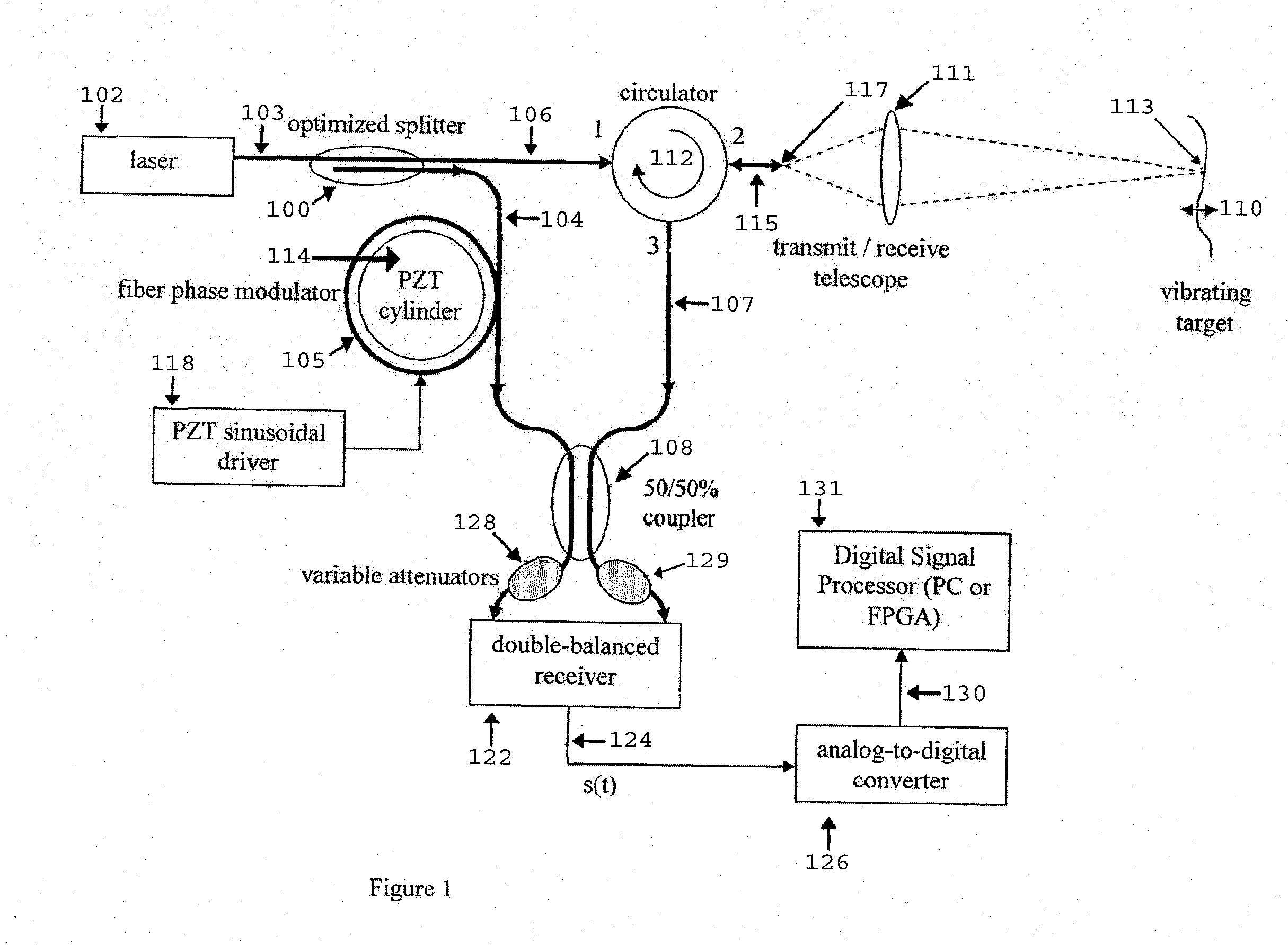
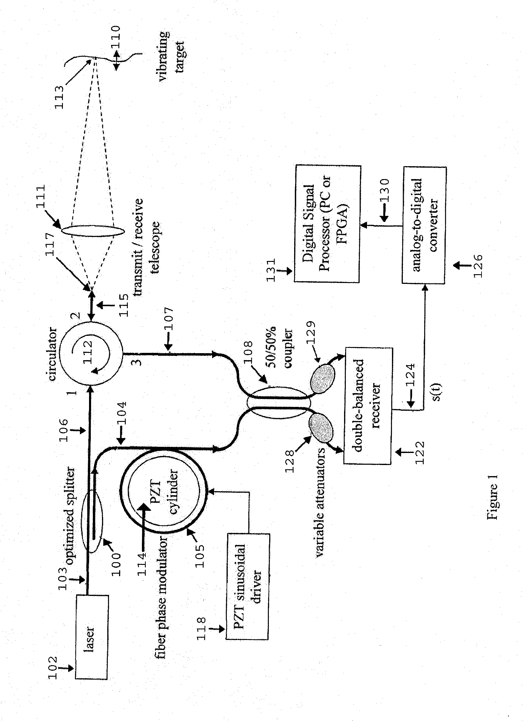
[0022]Interferometer: An interferometer based on a variant of the Mach-Zender interferometer includes a laser 102. A first beam splitter 100 in the interferometer separates a portion of a laser output 103 into a heterodyne reference beam 104 and a target beam 106. All beams described herein and in FIG. 1 are fundamental guided modes within polarization-maintaining single-mode fiber, except for the free-space portion indicated by dashed lines. A small portion of a source power is distributed to the reference beam 104 to overcome receiver noise; more than this amount causes unwanted shot-noise. The remaining power is distributed to the target beam 106 where it is necessary to overcome scattering and absorption, and path propagation loss from a target surface 110. Instead of a beam splitter directing energy to the target 110, a non-reciprocal optical circulator 112 is used. The non-reciprocal optical circulator 112 has the property of routing a reflected beam 11...


PUM


Abstract

An apparatus and method for non-determination of the surface velocity of a target using optical interference and Doppler shifting of the light reflected from the target are disclosed. It may be used to measure small-amplitude, acoustic frequency surface vibrations as well as non-periodic surface vibration.

Description

GOVERNMENT INTEREST[0001]The invention described herein may be manufactured, used, sold, imported, and / or licensed by or for the United States Government.BACKGROUND OF THE INVENTION[0002]Non-contact measurement of surface velocity can be done using an optical interference method and sensing the Doppler shift of reflected light from a target. If the target vibration is to be measured, the reflected light acquires a spectrum of sidebands from the range of vibrational frequencies at the target. This type of measurement differs in many details from that of a static, or quasi-static, velocity measurement such as in laser radar, or measurement of atmospheric aerosol velocities, although both rely on the same basic physical principles. In this specification, the invention is applied to measurement of small-amplitude, acoustic-frequency surface vibrations, but is also applicable to special cases of non-periodic velocities as well.DESCRIPTION OF THE PRIOR ART[0003]In past implementations, la...

Claims


Application Information

Patent Timeline
IPC IPC(8): G01B9/02
CPCG01H9/004G01S7/4818G01S7/491G01S17/58G01S7/497G01S17/36G01S7/4913
Inventor CHINN, STEPHEN R.HABERSAT, JAMES D.LIBBEY, BRADLEY
Owner UNITED STATES OF AMERICA THE AS REPRESENTED BY THE SEC OF THE ARMY
Why Eureka
Try Eureka