
De-tuning in wireless power reception

A wireless power and receiver technology, applied in different battery charging, electrical components, transmission systems, etc., can solve the problems of limiting the type of devices that can be charged, unable to adjust the fixed radiation power level, wasting power, etc.

Active Publication Date: 2012-06-13
QUALCOMM INC
View PDF6 Cites 30 Cited by
  • Summary
  • Abstract
  • Description
  • Claims
  • Application Information

AI Technical Summary

Problems solved by technology

This method has the disadvantage that the transmitting and receiving antennas must be very closely spaced (e.g. within a few thousandths of a meter)
[0009] For many wireless charging systems, the power transmitted from the power source is fixed to a single level, so it is often not possible to adjust the power level to accommodate devices with different maximum peak power levels
This situation limits the types of devices that can be charged
Another problem is that the fixed radiated power level cannot be adjusted based on the current battery level of the device
This situation wastes power because as the battery charges, it requires less and less power to complete the charge

Method used


Image

  • De-tuning in wireless power reception
  • De-tuning in wireless power reception
  • De-tuning in wireless power reception

Examples


Embodiment Construction

[0027] The word "exemplary" is used herein to mean "serving as an example, instance, or illustration." Any embodiment described herein as "exemplary" is not necessarily to be construed as preferred or advantageous over other embodiments.

[0028] The detailed description set forth below in connection with the accompanying drawings is intended as a description of exemplary embodiments of the invention and is not intended to represent the only embodiments in which the invention may be practiced. The term "exemplary" is used throughout this description to mean "serving as an example, instance, or illustration" and should not necessarily be construed as preferred or advantageous over other exemplary embodiments. The detailed description includes specific details for the purpose of providing a thorough understanding of the exemplary embodiments of the invention. It will be apparent to those skilled in the art that the exemplary embodiments of the invention may be practiced without...


PUM


Abstract

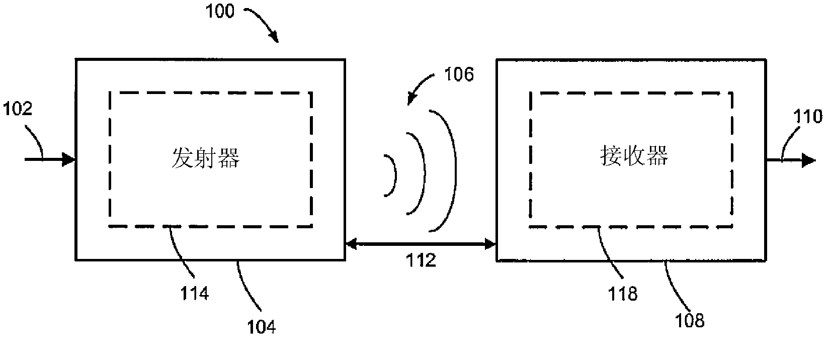
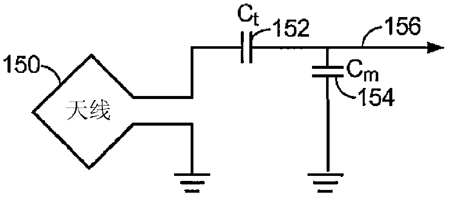
Exemplary embodiments are directed to wireless power transfer. A receiver (820) with a receive antenna (L2) couples with near field radiation in a coupling mode region. The receiver generates an RF signal at a resonant frequency responsive to the near field radiation. A de-tuning circuit (860) generates a variable impedance responsive to a control signal to modify the RF signal to a smaller amplitude or to a different resonant frequency. A rectifier (840) converts the modified RF signal to a DC signal. A comparator (850) creates a feedback loop by generating the control signal responsive to comparing the DC signal to a reference voltage (Vref). The de-tuning circuit may operate in digital mode or in linear mode with the feedback. An impedance element (R1) may be coupled to the de-tuning circuit to generate a voltage proportional to a current through the de-tuning circuit. The proportional voltage is rectified to a receive signal (1430) with information sent from a transmitter.

Description

[0001] Claim of priority under 35 U.S.C. §119 [0002] This application claims priority under 35 U.S.C. § 119(e): [0003] U.S. Provisional Patent Application No. 61 / 239,418, filed September 2, 2009, and entitled "LINEAR DE-TUNING INVENTION DISCLOSURE," the disclosure of which is hereby incorporated in its entirety Incorporated herein by reference. [0004] U.S. Provisional Patent Application No. 61 / 257,770, filed November 3, 2009, and entitled "DE-TUNING DEVICE CURRENT TO RECEIVE RADIO FREQUENCY SIGNALS," said provisional patent The disclosure of the application is hereby incorporated by reference in its entirety. technical field [0005] The present invention relates generally to wireless charging, and more particularly to devices, systems and methods related to distributing power to receiver devices that may be located in a wireless power system. Background technique [0006] Typically, each battery powered device (eg, wireless electronic device) requires its own char...

Claims


Application Information

Patent Timeline
IPC IPC(8): H02J5/00H04B5/00
CPCH04B5/0037H02J5/005H02J7/0047H02J50/40H02J50/80H02J50/90H02J50/12H04B5/79H02J50/20H02J50/50H04B5/24
Inventor 保罗·梅内戈利琳达·S·艾里什
Owner QUALCOMM INC
Learn More