Self-adapting variable-damping hydraulic pressure rubber vibration isolation device for automobile suspension

An automobile suspension and self-adaptive technology, applied in the direction of shock absorber, shock absorber-spring combination, spring/shock absorber, etc., can solve problems such as poor damping, poor adaptability, and invariable damping effect. Achieve the effect of preventing damping failure, good use value and compact structure

Active Publication Date: 2015-01-28
DFSK MOTOR LTD CHONGQING BRANCH CO
View PDF6 Cites 28 Cited by
  • Summary
  • Abstract
  • Description
  • Claims
  • Application Information

AI Technical Summary

Problems solved by technology

[0003] However, the fluid channels connecting the two hydraulic chambers on the existing radial hydraulic bushings are generally set on the rubber body, which not only easily deforms with the compression of the rubber body when subjected to radial impact loads, resulting in poor damping, or even loss of damping effect, and the damping effect produced by the fluid channel in the prior art is invariable, and the size of the damping hole is fixed. Under different impact load conditions, the damping effect is different and changes accordingly, and the adaptability is not good

Method used


Image

  • Self-adapting variable-damping hydraulic pressure rubber vibration isolation device for automobile suspension
  • Self-adapting variable-damping hydraulic pressure rubber vibration isolation device for automobile suspension
  • Self-adapting variable-damping hydraulic pressure rubber vibration isolation device for automobile suspension

Examples


Embodiment Construction

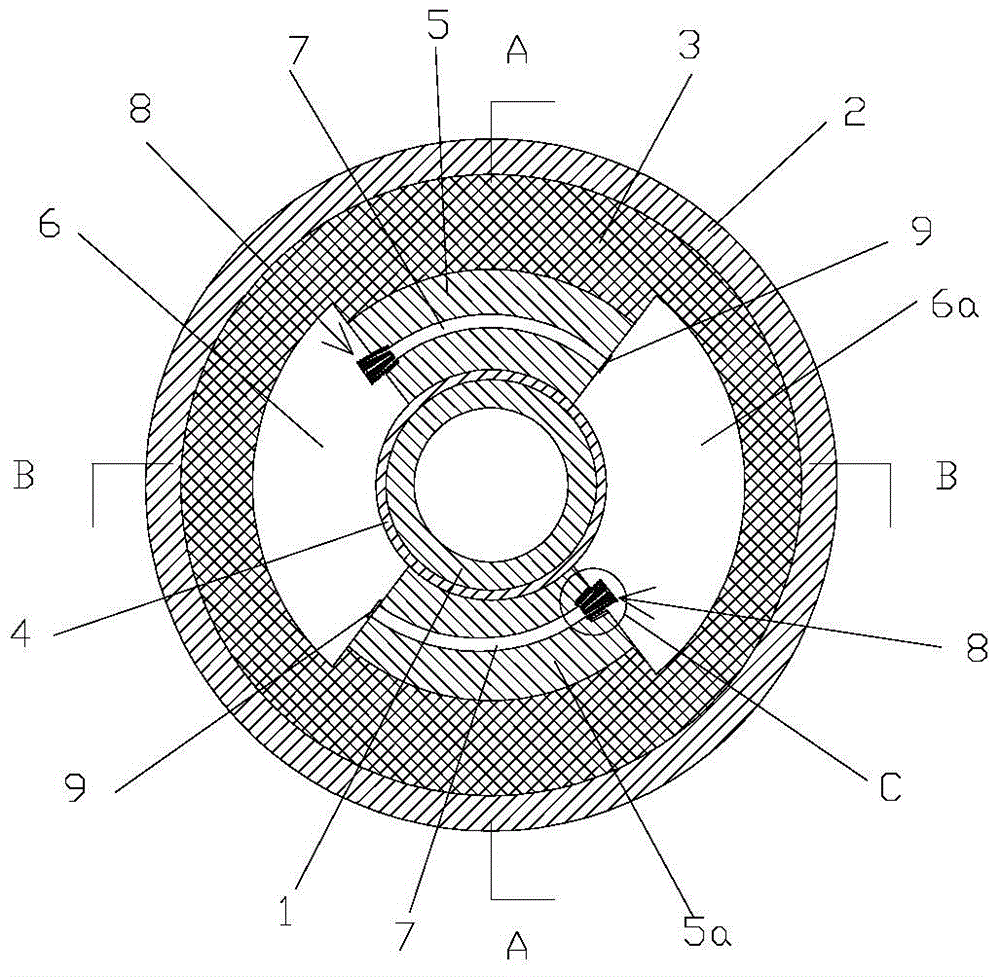
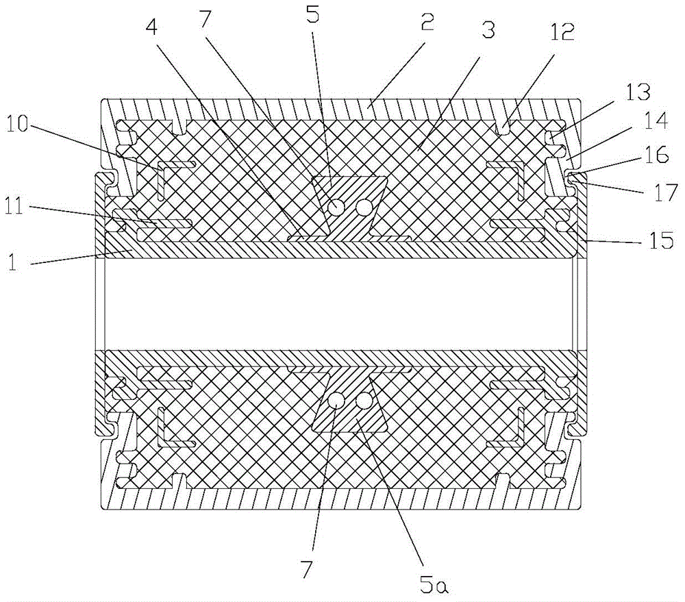
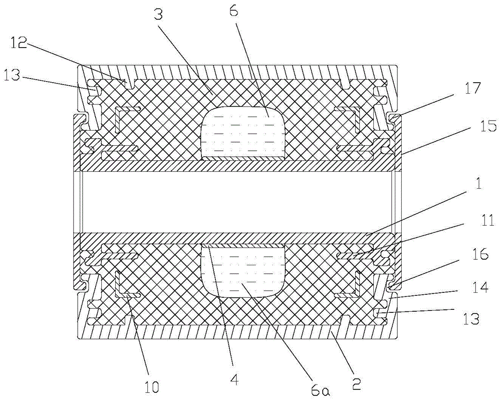
[0022] As shown in the figure: the adaptive variable damping hydraulic rubber vibration isolation device for automobile suspension in this embodiment includes an inner tube 1, an outer tube 2 and a rubber body 3 arranged between the inner tube 1 and the outer tube 2, and It includes a separating device arranged between the inner tube 1 and the rubber body 3. The separating device includes a fixed tube 4 fixed on the periphery of the inner tube 1 and an isolator I5 and an isolator II5a arranged outside the fixed tube 4. The rubber body 3 The space between the fixed pipe 4, the isolation body I5 and the isolation body II5a forms a hydraulic working chamber I6 and a hydraulic working chamber II6a, and the isolation body I5 and the isolation body II5a are respectively provided with a fluid channel 7 for connecting the two hydraulic working chambers;

[0023] The connecting end of the fluid channel 7 of the isolator I5 and the hydraulic working chamber I6 and the connecting end of t...


PUM


Abstract

The invention discloses a self-adapting variable-damping hydraulic pressure rubber vibration isolation device for an automobile suspension. The vibration isolation device comprises an inner pipe, an outer pipe, a rubber body arranged between the inner pipe and the outer pipe, a separation device arranged between the inner pipe and the rubber body, wherein damping adjustment components which are used for adjusting damping force according to pressure are respectively arranged at a communicating end of a fluid flow passage of an isolator I and a hydraulic pressure working chamber, and at a communicating end of a fluid flow passage of an isolator II and a hydraulic pressure working chamber II; the damping adjustment components are arranged, under the working conditions of high frequency and small amplitude, a spring is not compressed or rarely compressed, and damping fluid flows into the fluid flow passages from the outer side of a plunger, so that the requirements for vibration reduction and noise reduction with low rigidity and small damping are satisfied; under the working conditions of low frequency and large amplitude, the inner diameter of a fluid through hole is far smaller than the hole diameter of the fluid flow passages, so that the pressure is increased, and the fluid hole diameter is decreased; therefore, at this moment, the damping force is greatly improved. Compared with an existing rubber lining, the vibration isolation device disclosed by the invention can completely satisfy the requirements of vibration reduction and noise reduction with high rigidity and high damping under the working conditions of low frequency and large amplitude.

Description

technical field [0001] The invention relates to the field of automobile suspension vibration reduction, in particular to an adaptive variable damping hydraulic rubber vibration isolation device for automobile suspension. Background technique [0002] In the current production process of the automobile industry, in order to greatly reduce the vibration of the automobile chassis during driving, the connection between the chassis and the suspension is often changed into a flexible connection. Among them, the most important flexible connection method is through the suspension parts. The end connection points are provided with rubber bushings. The radial type hydraulic bushing is a kind of rubber bushing. Two hydraulic chambers arranged radially opposite to each other are connected by a fluid channel. When a radial impact load or vibration occurs, the damping mucus circulates in the two hydraulic chambers to generate damping. Force, in order to achieve the purpose of vibration i...

Claims


Application Information

Patent Timeline
Patent Type & Authority Applications(China)
IPC IPC(8): F16F13/26F16F13/14
CPCF16F13/14F16F13/26
Inventor 许林
Owner DFSK MOTOR LTD CHONGQING BRANCH CO
Why Eureka
Try Eureka