Flat-plate lighting device

a technology of lighting device and flat plate, which is applied in the direction of fixed installation, lighting and heating equipment with built-in power, etc., can solve the problems of inability to meet the needs of users

Inactive Publication Date: 2008-12-04
CHU KO CHIEN
View PDF3 Cites 91 Cited by
  • Summary
  • Abstract
  • Description
  • Claims
  • Application Information

AI Technical Summary

Benefits of technology

[0005]The primary purpose of the present invention is to provide a flat-plate lighting device designed as an integral part using the concept of module and conception of being compact and collective to come up with a structure of ultra thin, LED lighting device that permits extension of the number of lamp body to correct problems found with the prior art.

Problems solved by technology

However, the energy resource is very limited.
Solar energy is an inexhaustible energy source, and the cheapest one.
As a result, brighter luminance is realized but the durability is compromised.
Other installations having the solar energy moudle and the lighting device separately provided however complicate in assembly work while failing to fit in the view of the landscape; furthermore, each type of those installations is specially designed to prevent it from coping assembly requirements or creating significant changes.
The prior art has affected both applicability and adaptability of the lighting device in generally.

Method used


Image

  • Flat-plate lighting device
  • Flat-plate lighting device
  • Flat-plate lighting device

Examples


Embodiment Construction

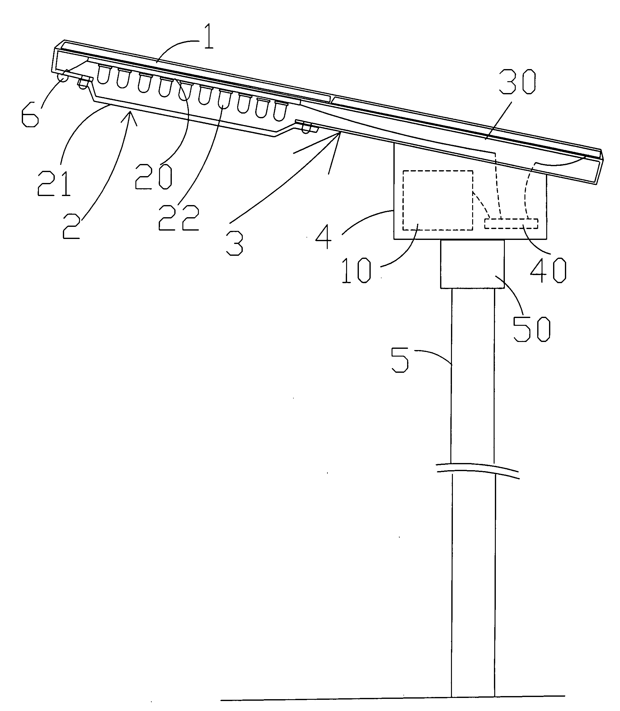
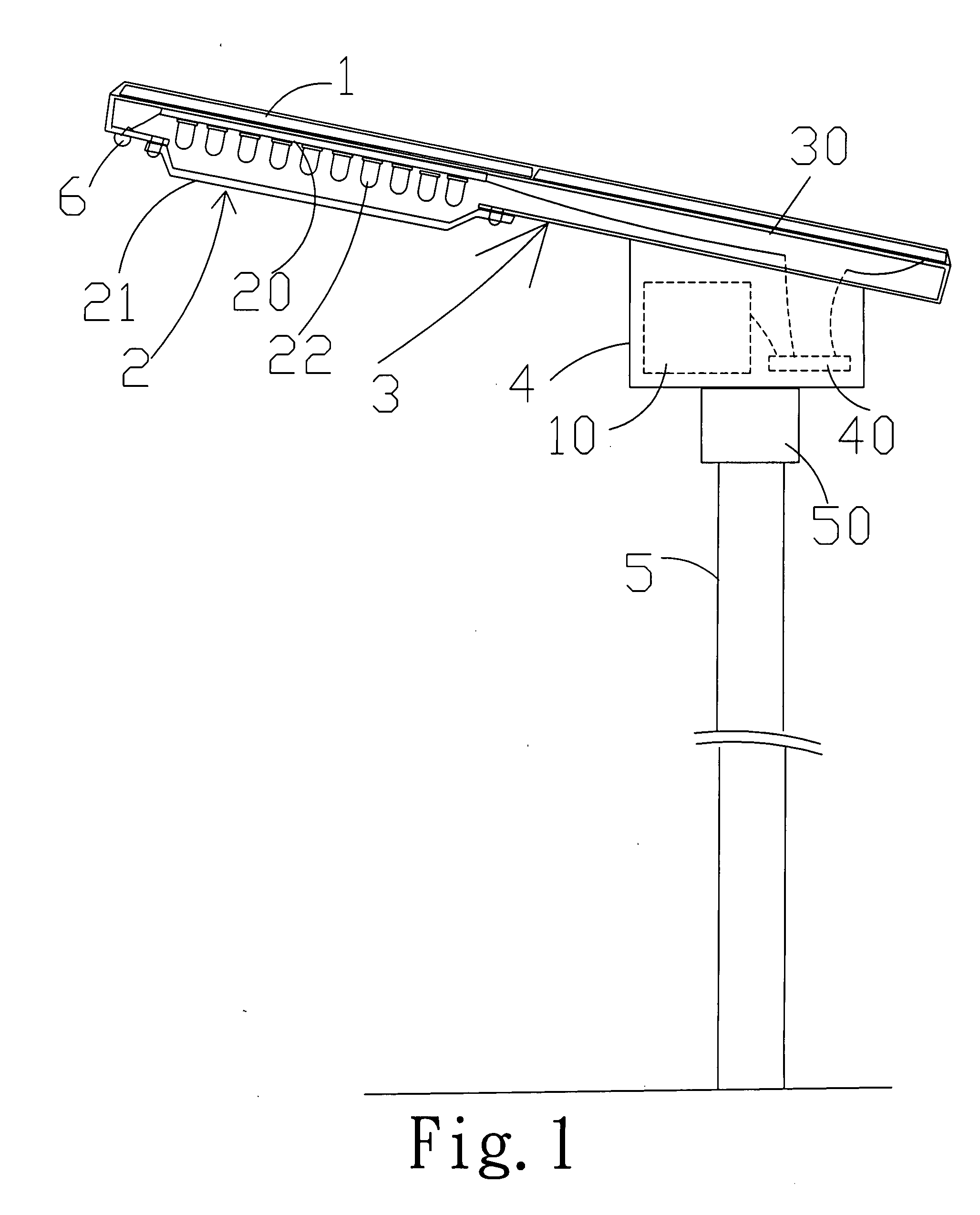
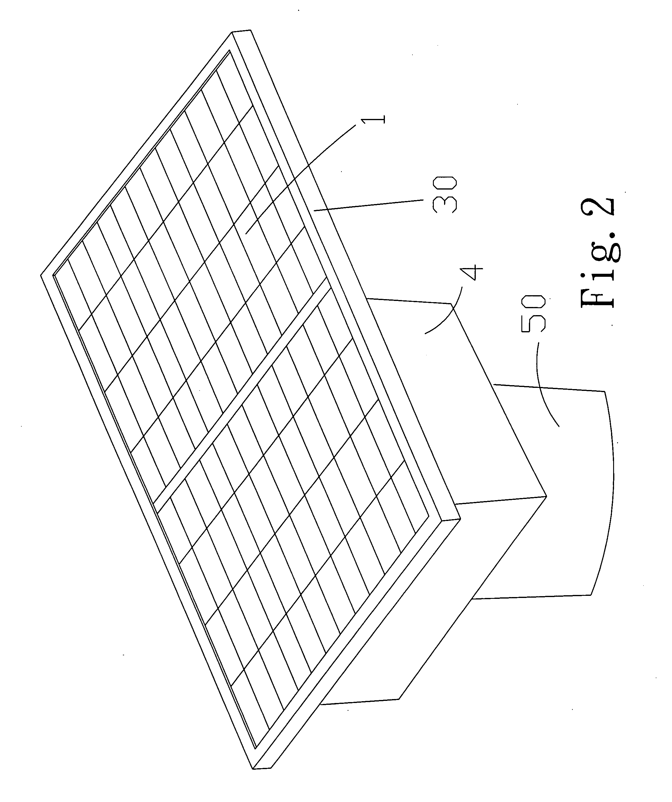
[0020]A flat-plate lighting device of the present invention as illustrated in FIGS. 1 through 12. The present invention includes a lamp body 3 and a lamp post 5 connected to each other; the lamp body 3 relates to a flat-plate frame 30 having on its top disposed with a sheet solar moudle 1 arranged in a pattern of matrix; a light-emitting area and an accommodation area are disposed inner-bottom of the frame 30, the light-emitting area contains one or a plurality of lighting unit 2 comprised of multiple light emitting diodes (LEDs); the accommodation area relates to a thicker box 4 containing a solar cell 10 and a circuit board 40, the circuit board 40 receives and converts sunlight energy from the solar moudle 1 into electric energy to be stored in the solar cell 10; the solar cell 10 is activated to supply power to the lighting unit 2 when a electro-optical sensor 6 detects insufficient ambient luminance; and a sleeve 50 is provided to the bottom of the box for connecting the box 4 ...


PUM


Abstract

A flat-plate lighting device comprising a lamp body and a lamp post; the lamp body related to a flat-plate frame having on its top disposed with a sheet matrix-like arrangement of a solar moudle, and on its inner-bottom connected to a light emitting area and a accommodation area with the lighting emitting area comprised of one or a plurality of lighting unit of LED and the accommodation area being related to a thicker box; the box contains a solar cell and a circuit board, the circuit board converts the sunlight energy from the solar moudle into electric energy and stored in the solar cell; the power is supplied to the lighting unit once a electro-optical sensor detects insufficient ambient luminance; and a power monitor circuit is added to the circuit board.

Description

BACKGROUND OF THE INVENTION[0001](a) Field of the Invention[0002]The present invention is related to a lighting device, and more particularly, which use solar powered be a flat-plate type frame and let LED lighting unit combination mounted to a lamp post lantern in building or street-light or garden-light.[0003](b) Description of the Prior Art[0004]Electric appliances and computer have become a must today thanks to rapid development of modern technology. Lighting during night hours not only serves for illumination use but also decoration and landscaping purposes. However, the energy resource is very limited. Petrol oil as the most important energy source is about to be consumed up if not wasted. Solar energy is an inexhaustible energy source, and the cheapest one. Many people with visions have been aggressively promoting the application to this regard. Whereas the solar energy is essentially applied on a wafer type collector, many lighting devices operating on solar energy generally...

Claims


Application Information

Patent Timeline
Patent Type & Authority Applications(United States)
IPC IPC(8): F21L4/08
CPCF21S8/086F21S9/035F21V23/0442F21Y2101/02F21S9/037F21W2131/103F21Y2115/10Y02B20/72
Inventor CHU, KO-CHIEN
Owner CHU KO CHIEN
Why Eureka
Try Eureka