

Apparatus for transferring substrates
a technology for transferring substrates and apparatuses, applied in the direction of instruments, transportation and packaging, optics, etc., can solve the problems of reducing productivity and reducing yield
- Summary
- Abstract
- Description
- Claims
- Application Information
AI Technical Summary
Benefits of technology
Problems solved by technology
Method used
Image

Examples
first embodiment
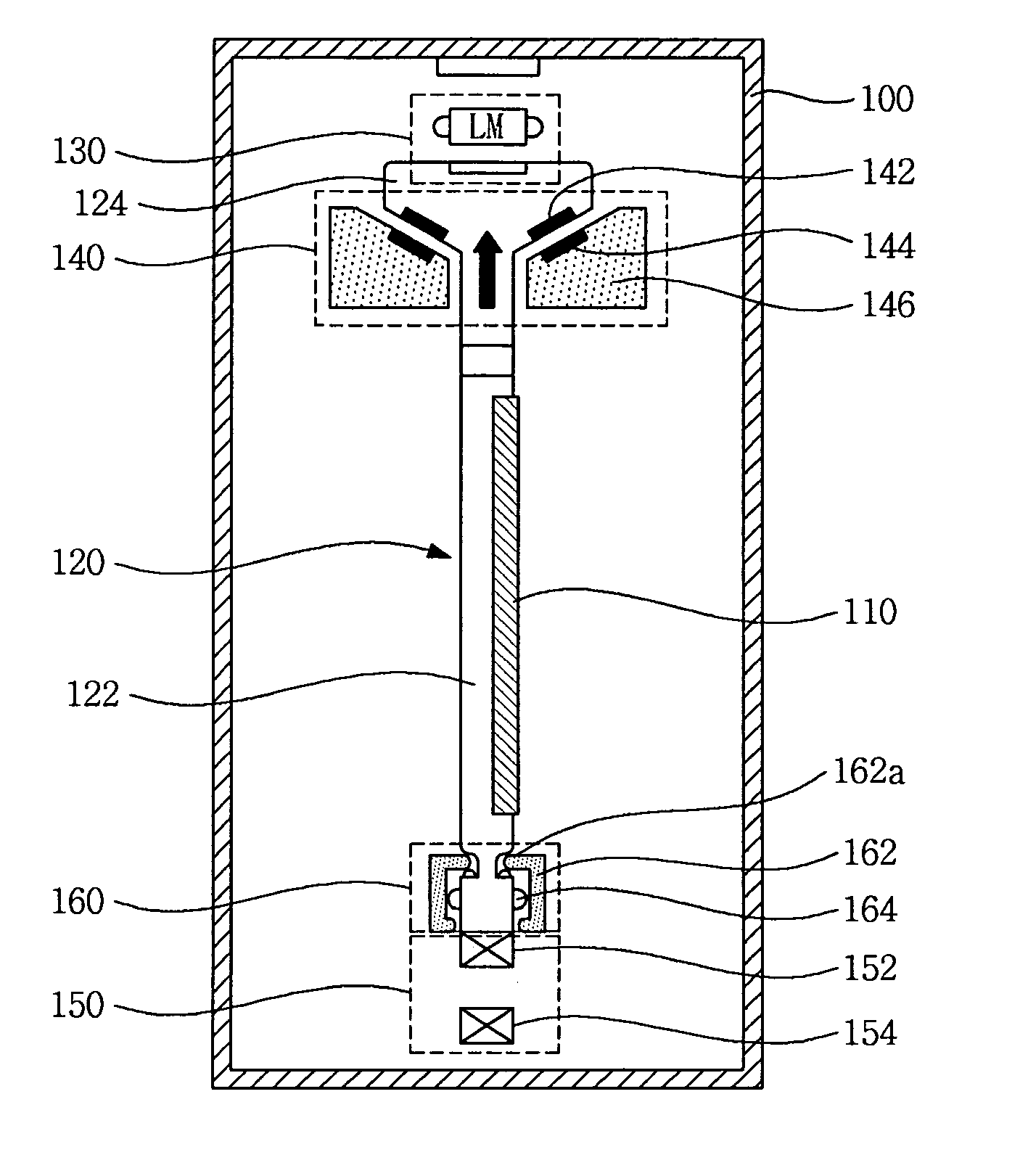
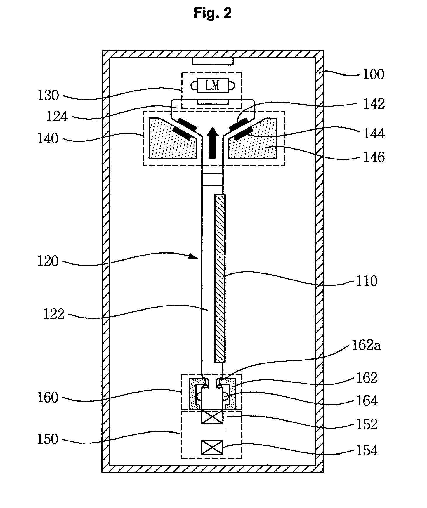
[0029]FIG. 2 illustrates a cross section of an apparatus for transferring substrates according to the invention. FIG. 3 illustrates a squint view of an apparatus for transferring substrates illustrated in FIG. 2 and FIG. 4 illustrates a front view of an apparatus for transferring substrates illustrated in FIG. 2.
[0030]With reference to FIGS. 2 through 4, an apparatus for transferring substrates according to the first embodiment of the invention includes a carrier 120 to which substrates 110 are loaded; an upper transfer unit 130 transferring the carrier 120 horizontally, a lower transfer unit 150 maintaining the lower body of the carrier 120 at the horizontal in a non-contact status, a magnetic levitation module 140 levitating the carrier 120 magnetically, and a lower damper unit installed to the lower body of the carrier 120.
[0031]The carrier 120 includes a body 122 to which a substrate 110 is mounted vertically and a head 124 having an inclination part 124A whose diameter enlarges...
second embodiment
[0062]FIG. 6 illustrates a cross section of an apparatus for transferring substrates according to the invention. FIG. 7 illustrates a squint view of the apparatus for transferring substrates illustrated in FIG. 6 and FIG. 8 is a front view of the apparatus for transferring substrates illustrated in FIG. 6.
[0063]An apparatus for transferring substrates according to a second embodiment of the invention transfers the carrier 220 horizontally by levitating the carrier 220 by using push force generated between magnets.
[0064]At this time, push force generating levitation force causes lateral force which inclines a subject in one direction as well as the levitation force. Such lateral force becomes large as the levitation force enlarges.
[0065]Accordingly, an apparatus for transferring substrates according to the second embodiment of the invention reduces inclination phenomena generated by lateral force by applying a damper at the upper part of the carrier 220, thereby providing a stable ca...
third embodiment
[0080]FIG. 9 illustrates a cross section of an apparatus for transferring substrates according to the invention. FIG. 10 illustrates a squint view of an apparatus for transferring substrates illustrated in FIG. 9 and FIG. 1 illustrates a front view of an apparatus for transferring substrates illustrated in FIG. 9.
[0081]The structure of an apparatus for transferring substrates according to the third embodiment of the invention is a combination of the structure of an apparatus for transferring apparatus according to the first embodiment and the structure of an apparatus for transferring substrates according to the second embodiment, having both a lower damper unit 360 and an upper damper unit 370 at the lower and upper body of a carrier 320.
[0082]Referring to FIG. 9 to be more specific, an apparatus for transferring substrates according to the third embodiment of the invention includes a carrier 320 to which substrates 310 are loaded; an upper transfer unit 330 transferring the carrie...
PUM
 Abstract
Description
Claims
Application Information