
Therapeutic knee brace having pressure applicators

Inactive Publication Date: 2008-12-04
FRISHBERG DOV
View PDF6 Cites 6 Cited by
  • Summary
  • Abstract
  • Description
  • Claims
  • Application Information

AI Technical Summary

Benefits of technology

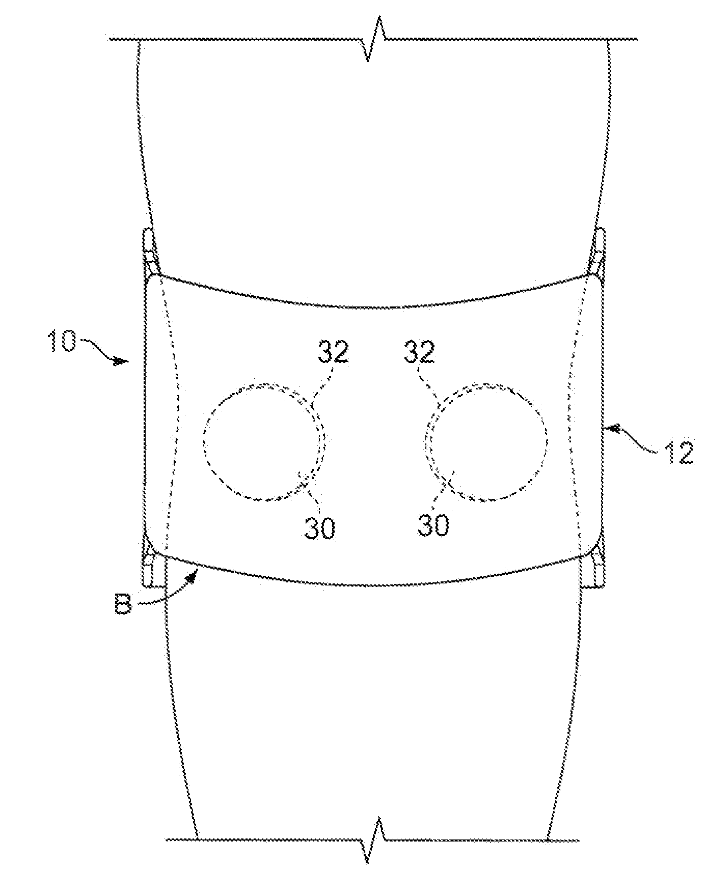
[0007]The present invention also provides a method for facilitating healing of a knee joint injury using the brace. The method includes the step of securing the body against the knee such that the applicators substantially nestle an associated patella of the knee and such that at least one of the applicators applies pressure against a joint in the knee.

Problems solved by technology

As a result, the knee joint KJ may become destabilised and may therefore require a brace to be worn for support, even after surgical correction of the injury.
Many of these braces suffer from design shortcomings which exacerbate the knee injuries that lead users to wear such braces in the first place, thereby compromising any therapeutic value they may have.
These design shortcomings are especially problematic when the injured ligament(s), or other soft tissue (e.g., cartilage) is adversely affected.

Method used


Image

  • Therapeutic knee brace having pressure applicators
  • Therapeutic knee brace having pressure applicators
  • Therapeutic knee brace having pressure applicators

Examples


Embodiment Construction

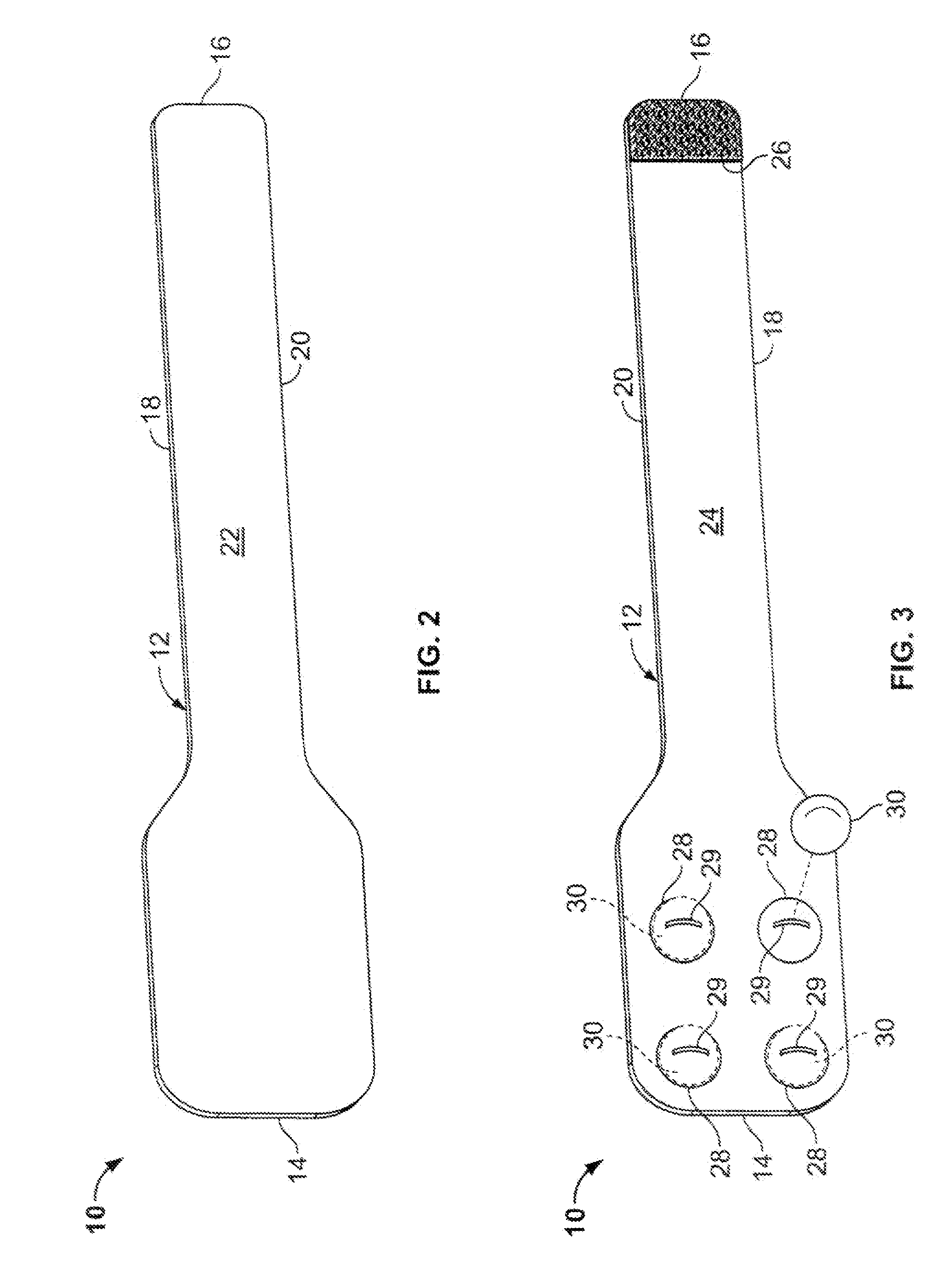
[0016]FIGS. 2-4 illustrate a knee brace 10 constructed in accordance with an exemplary embodiment of the present invention. The knee brace 10 includes a body, shown as an elongated member 12 having a pair of ends 14, 16, a pair of sides 18, 20, an outer surface 22 (see FIG. 2) and an inner surface 24 (see FIG. 3). The elongated member 12 has a similar construction to that of conventional athletic knee braces (e.g., such as those marketed by Becton Dickinson and Company, Franklin Lakes, N.J. under the trademark Tru-Fit®), and is preferably made of a breathable, lightweight, flexible and elastic material (or materials), such as those used in making conventional braces. As shown in FIGS. 2 and 3, the end 14 is preferably wider than the end 16. This shape facilitates the wrapping of the brace 10 about a user's knee joint KJ, as shown in FIG. 4. A fastener 26 is affixed to the inner surface 24 adjacent the end 16 (see FIG. 3) such that the end 16 can be secured to the outer surface 22 ad...


PUM


Abstract

A brace for a knee joint including an elongated member and pressure applicators disposed thereon. Each of the pressure applicators may be inserted into a corresponding, closeable pouch on an inner surface of the elongated member. The pouches are arranged on the inner surface to situate the respective pressure applicators in the spaces between the various ligaments, cartilage and bones of the knee joint, so as to prevent applying pressure directly to these tissues and the pain caused thereby. A user may choose to insert all, or some, of the pressure applicators in their respective pouches, depending on nature of the injury. A method using the knee brace to facilitate healing of a knee joint injury is also disclosed.

Description

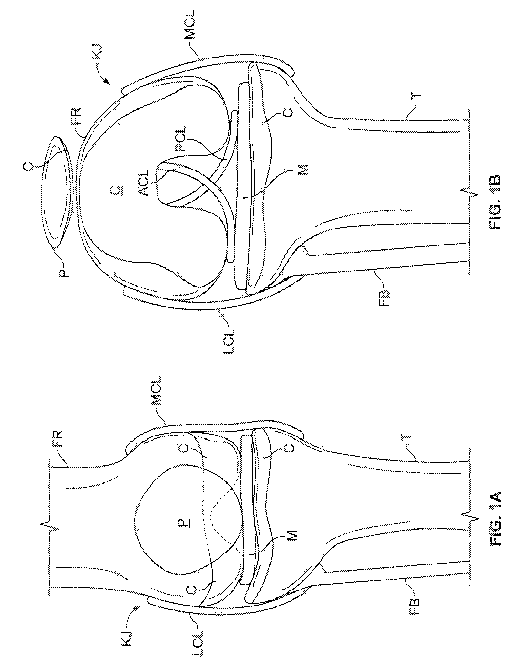
FIELD OF THE INVENTION[0001]The present invention relates to therapeutic knee braces and, more particularly, to therapeutic knee brace having pressure applicators.BACKGROUND OF THE INVENTION[0002]Reference is made to FIGS. 1A and 1B, which are anatomical representations of a right human knee joint KJ in extension and in flexion, respectively. The femur FR and tibia T bones of the leg meet to form the knee joint KJ. The fibula FB extends along the lateral side of the tibia T and joins the tibia T at the top, or head, thereof. The patella P (i.e., kneecap) is disposed proximate the femur FR and protects the front of the knee joint KJ. Cartilage C covers the articulating surfaces of the patella P, femur FR and tibia T, and acts to cushion these bones. The meniscus M is a layer of cartilage disposed between the femur FR and the tibia T and further cushions these bones.[0003]With continued reference to FIGS. 1A and 1B, the ligaments of the knee joint KJ connect the associated bones to st...

Claims


Application Information

Patent Timeline
IPC IPC(8): A61F5/00
CPCA61F5/0106A61F5/30A61F2005/0176
Inventor FRISHBERG, DOV
Owner FRISHBERG DOV
Learn More