Coupling System

Inactive Publication Date: 2008-12-11
KONINKLIJKE PHILIPS ELECTRONICS NV
View PDF15 Cites 52 Cited by
  • Summary
  • Abstract
  • Description
  • Claims
  • Application Information

AI Technical Summary

Benefits of technology

[0010]An object of the present invention is to provide a coupling system which is operable to accommodate relative spatial movement of coup

Problems solved by technology

However, complications can arise when the modules need to spatially moved relative to the back plane or motherboard when in use.
A problem with such flexible leads is that their conductors can work-harden, namely develop fatigue cracks, which can result in fracture and hence in at least partial loss of electrical connection.
Another problem is that such flexible leads are often an inconvenience in that they can obstruct desired movement.
In contemporary systems requiring appreciable electrical power transfer, flexible leads can become impractically bulky.
When a variable load is coupled to the secondary winding, for example a variable load coupled via switching thyristors or switching power transistor devices for controlling power to the load in a pulse width modulated (PWM) mode of operation, transient surges of power are encountered at the primary winding and can cause potential interference.
Such interference can be especially

Method used


Image

  • Coupling System
  • Coupling System
  • Coupling System

Examples


Embodiment Construction

[0037]In describing the present invention, a coupling system will be described and then various diverse practical applications of the coupling system will be described.

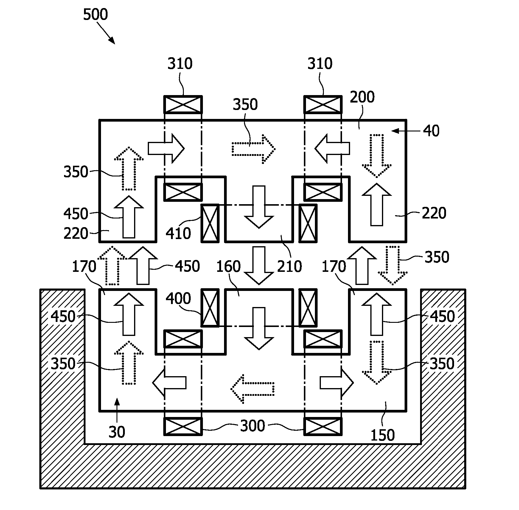
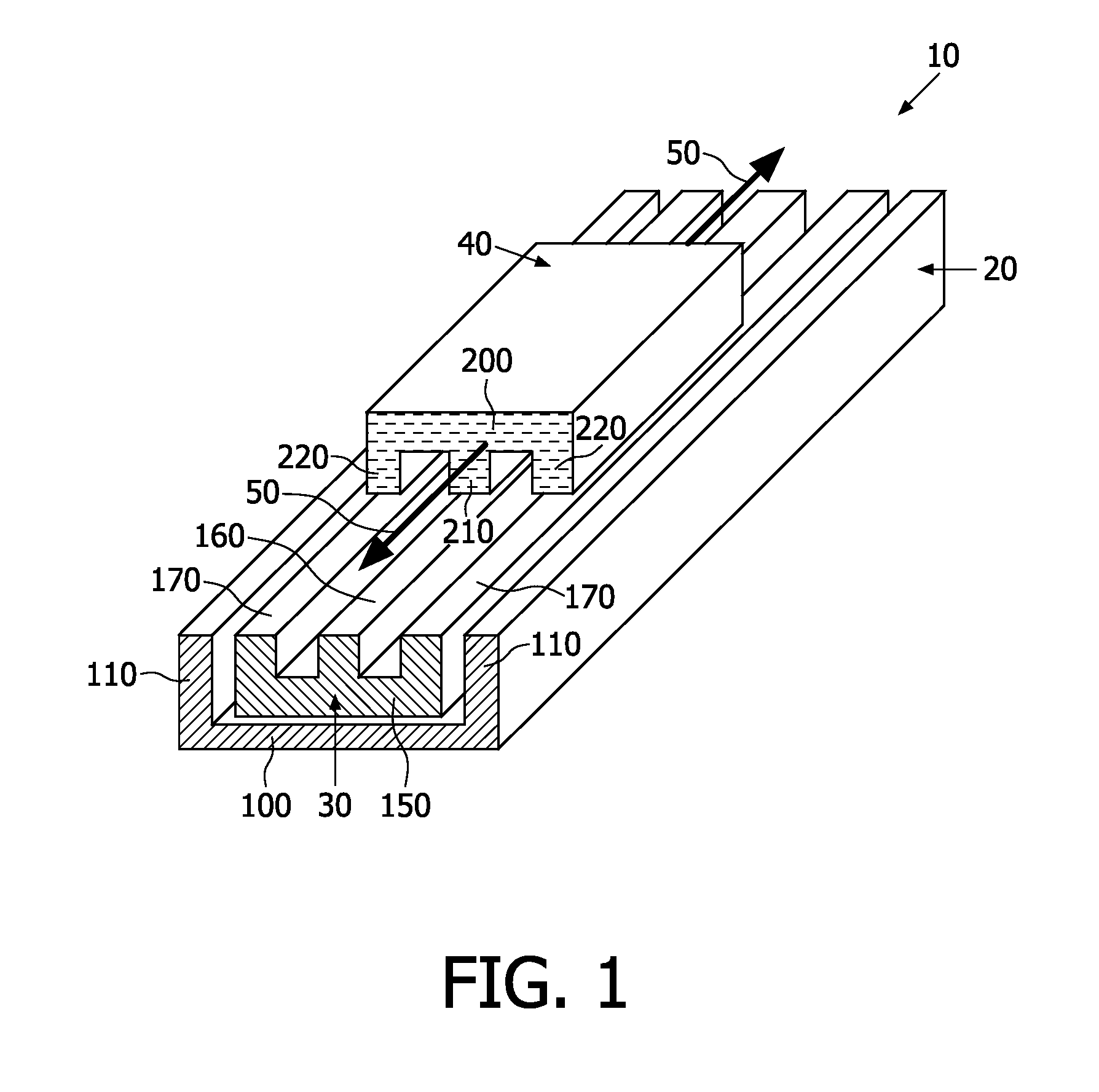
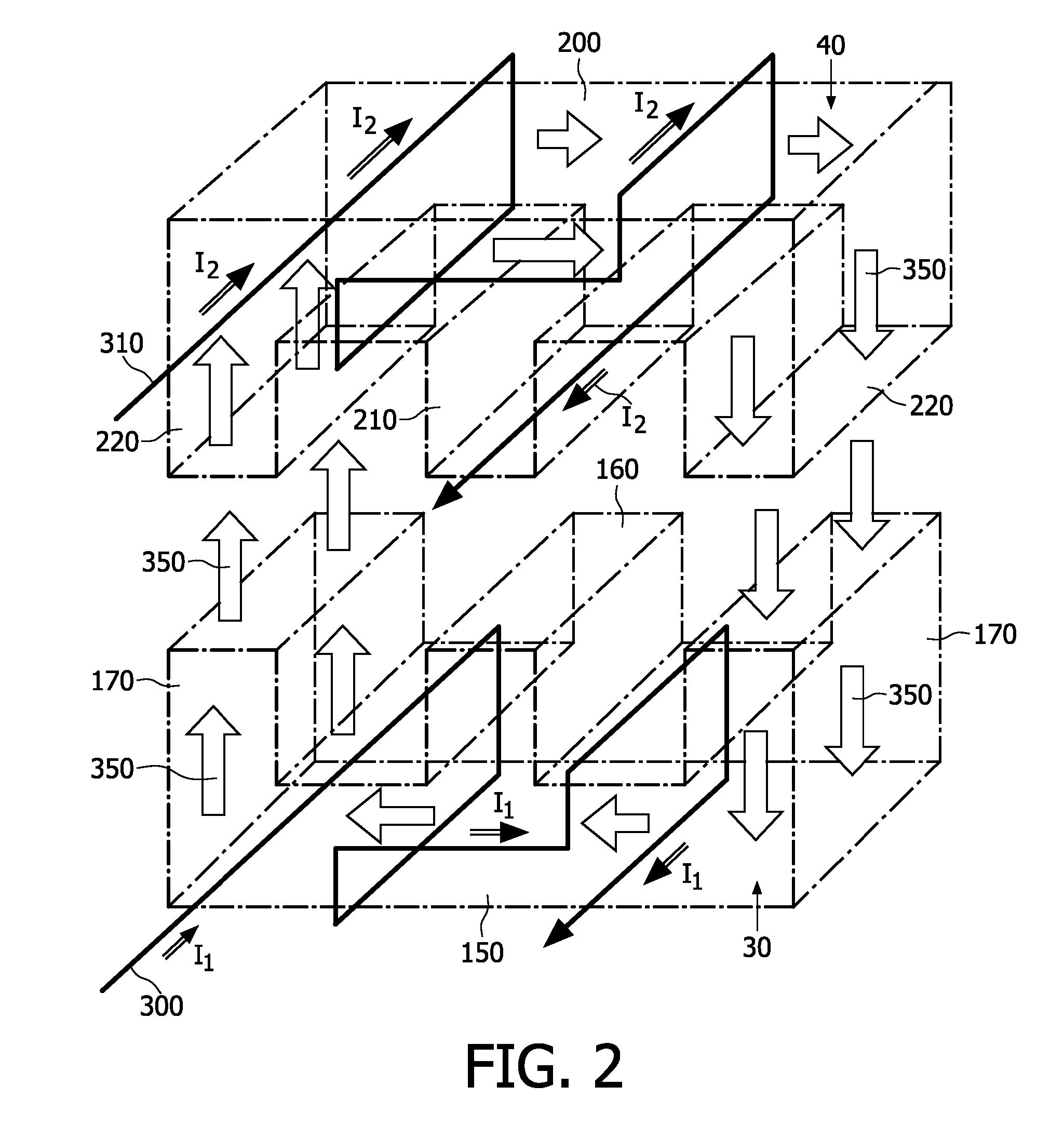
[0038]Referring to FIG. 1, there is shown a magnetic coupling device adapted for implementing a coupling system pursuant to the present invention. The magnetic coupling device is indicated generally by 10. The device 10 comprises an elongate housing 20, a first core 30 and a second core 40. The second core 40 is operable to be moved in operation in directions denoted by arrows 50 relative to the first core 30 so that complementary limbs of the cores 30, 40 remain mutually aligned.

[0039]The housing 20 is implemented as a “U”-shaped channel having a base 100 and two side walls 110. Optionally, the channel is fabricated from a plastics material, an extruded non-ferrous metal such as aluminum (aluminum), non-magnetic stainless steel, or from a ceramic material. The housing 20 is operable to accommodate therein the first c...


PUM


Abstract

There is elucidated a device (10) comprising first and second magnetic cores (30, 40; 30a, 30b, 30c, 40a, 40b, 40c) forming a magnetic circuit. The circuit includes a first set of electrical windings (300, 310) for magnetically coupling a first electrical signal through the device (10) via a first magnetic path (350) in the circuit. The circuit includes a second set of electrical windings (400, 410) for magnetically coupling a second electrical signal through the device (10) via a second magnetic path (450) in the circuit. The paths (350, 450) are partially spatially intersecting. The sets of windings (300, 310, 400, 410) are configured so that: (a) the first set of windings (300, 310) is sensitive to magnetic flux in the first magnetic path (350), and insensitive to magnetic flux in the second magnetic path (450); and (b) the second set of windings (400, 410) is sensitive to magnetic flux in the second magnetic path (450), and insensitive to magnetic flux in the first magnetic path (350). The first and second cores (30, 40; 30a, 30b, 30c, 40a, 40b, 40c) enable relative motion (50) there between whilst coupling the signals through the circuit. The device (10) is beneficially employed in a medical system (800).

Description

FIELD OF THE INVENTION[0001]The present invention relates to coupling systems for concurrently conveying electrical power and data signals. Moreover, the present invention also relates to coupling devices operable to couple electrical power and data signals. Furthermore, the invention relates to methods of concurrently conveying electrical power and data signals. Additionally, the invention relates to apparatus including such coupling systems and devices.BACKGROUND OF THE INVENTION[0002]Many contemporary systems include configurations of electrical devices, which are operable to interact by way of information, and data exchange there between, but also need to be provided with electrical power to function. For example, contemporary computer systems often include several modules which are coup able to a computer back plane or mother board by way of electrical connectors; the electrical connectors include power lines for providing electrical power to the modules as well as signal lines...

Claims


Application Information

Patent Timeline
IPC IPC(8): H01F38/14
CPCA61C1/0015A61G7/0503A61G13/107A61G15/10H01F38/14H01F2038/143H02J5/005H02J50/40H02J50/10H02J2310/23H02J50/12
Inventor JANSEN, GERARDUS LUCIEN MATHIDUSLANGERAK, MARIELLE JOHANNAHOBO, GIJSBERT
Owner KONINKLIJKE PHILIPS ELECTRONICS NV
Why Eureka
Try Eureka