
High gain RFID tag antennas

a radio frequency identification and high gain technology, applied in the field of improving the gain of radio frequency identification tags, can solve the problems of low efficiency of more reasonable sized antennas at such low frequencies, and achieve the effect of improving the reading distance of passive rfid tags

Inactive Publication Date: 2008-12-11
SHENLOON KIP ASSETAB
View PDF5 Cites 22 Cited by
  • Summary
  • Abstract
  • Description
  • Claims
  • Application Information

AI Technical Summary

Benefits of technology

[0011]According to another aspect, a method of improving the reading distance of a passive RFID tag is provided. The method involves attaching an RFID tag to a surface and subsequently adding parasitic elements substantially parallel to the longitudinal axis of the RFID tag's antenna. Advantageously, the addition of the parasitic elements can occur without direct modifications to the RFID tag. Thus, commercially-available tags without parasitic elements can have the parasitic elements added after manufacture of a tag or after attachment of a tag to an object. In other embodiments, the parasitic elements can be added during tag manufacture.

Problems solved by technology

These systems suffer from low efficiency of more reasonably sized antennas at such low frequencies.

Method used


Image

  • High gain RFID tag antennas
  • High gain RFID tag antennas
  • High gain RFID tag antennas

Examples


Embodiment Construction

[0023]The present invention is now described with reference to the drawings, wherein like reference numerals are used to refer to mean serving as an example, instance, or illustration. Any aspect or design described herein as “exemplary” is not necessarily to be construed as preferred or advantageous over other aspects or designs. Rather, use of the word exemplary is intended to present concepts in a concrete fashion. As used in this application, the term “or” is intended to mean an inclusive “or” rather than an exclusive “or”. That is, unless specified otherwise, or clear from context, “X employs A or B” is intended to mean any of the natural inclusive permutations. That is, if X employs A; X employs B; or X employs both A and B, then “X employs A or B” is satisfied under any of the foregoing instances. In addition, the articles “a” and “an” as used in this application and the appended claims should generally be construed to mean “one or more” unless specified otherwise or clear fr...


PUM


Abstract

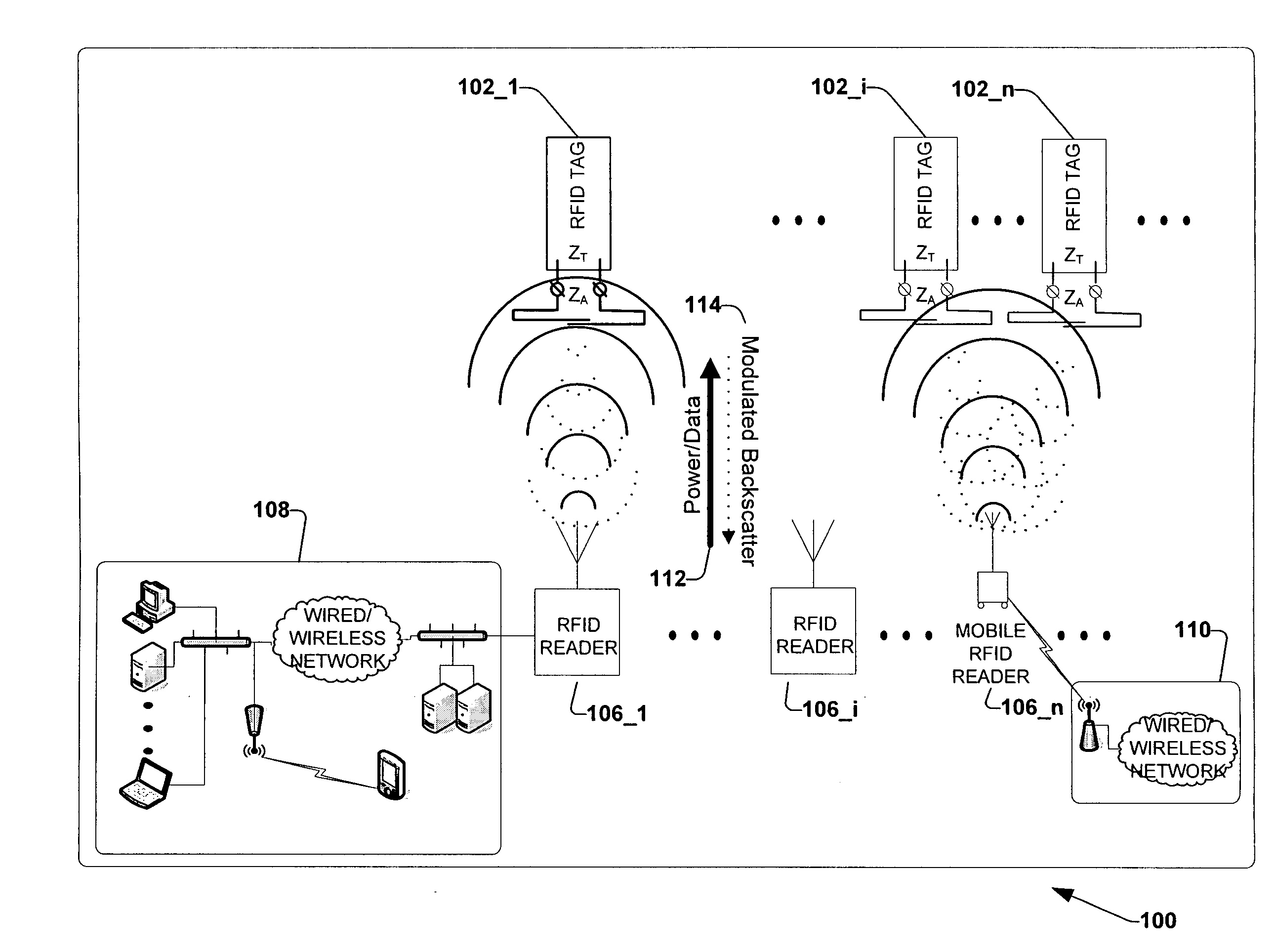
A non-pervasive modification to radio frequency identification (RFID) tag antennas is provided that can double the tag's reading range distance. Parasitic elements, such as a reflector and one or more directors, are added at appropriate separations to form a Yagi antenna. As a result, the antenna's gain is increased and consequently so is the RFID tag's reading range. The tag antenna's gain can be achieved without directly connecting to or modifying the existing RFID tag. However, since directionality is increased, multiple RFID tags can be attached to an object so that the tagged object can be read from multiple directions.

Description

CROSS REFERENCE TO RELATED APPLICATIONS[0001]This non-provisional application claims benefit under 35 U.S.C. § 119(e) of U.S. provisional Application No. 60 / 942,596, filed Jun. 7, 2007, which is hereby incorporated by reference.TECHNICAL FIELD[0002]The subject disclosure relates generally to improving the gain of radio frequency identification tags, such as passive ultra high frequency radio frequency identification tags.BACKGROUND[0003]Recently, radio frequency identification (RFID) systems have become popular for commercial use. Applications include for example intelligent transportation systems (e.g., automobile theft prevention, automated parking, high speed toll collection, traffic management), commerce (e.g., factory automation, inventory management and tracking, merchandise theft prevention, tracking and library book theft prevention, parcel and document tracking, livestock tracking, dispensing goods, controlled ski lift access, fare collection), and security (e.g., access co...

Claims


Application Information

Patent Timeline
Patent Type & Authority Applications(United States)
IPC IPC(8): H04Q5/22
CPCG06K7/10178G06K19/07749H01Q1/2225H01Q19/30H04Q9/00H04Q2209/47G06K19/077H01Q1/24H01Q1/38
Inventor CHENG, CHI HOMURCH, ROSS DAVID
Owner SHENLOON KIP ASSETAB
Learn More