
Flat panel display device

a flat panel display and display device technology, applied in the field can solve the problems of picture quality degradation and picture quality degradation of flat panel display devices, and achieve the effect of reducing resistance differences

Active Publication Date: 2008-12-11
SAMSUNG DISPLAY CO LTD
View PDF3 Cites 24 Cited by
  • Summary
  • Abstract
  • Description
  • Claims
  • Application Information

AI Technical Summary

Benefits of technology

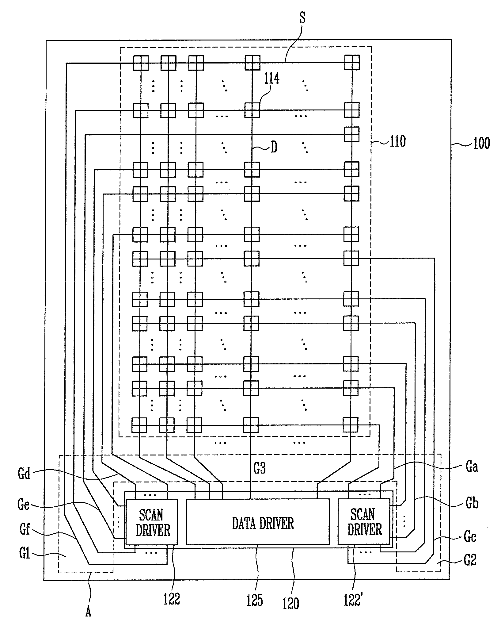
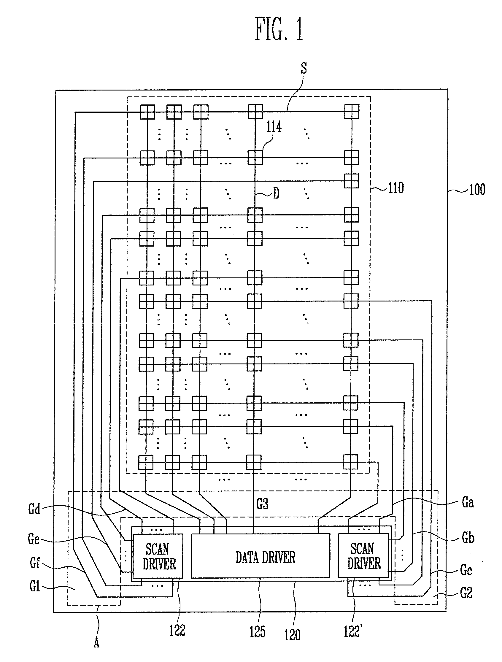
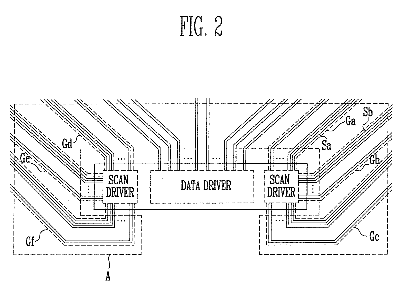
[0013]Accordingly, aspects of the present invention are designed to solve such drawbacks of the related art, and an aspect of the present invention is to provide a flat panel display device capable of reducing a resistance difference arising from differences in the lengths of signal lines and to design stability into a resistance value of the signal lines arranged in edges of wire groups that diverge from a driving circuit unit.

Problems solved by technology

The difference in resistance values results in deterioration of picture quality in the flat panel display devices.
The resistance difference will result in a deterioration of quality in the pictures due to a lack of precise voltage control.

Method used


Image

  • Flat panel display device
  • Flat panel display device
  • Flat panel display device

Examples


Embodiment Construction

[0027]Reference will now be made in detail to the aspects of the present invention, examples of which are illustrated in the accompanying drawings, wherein like reference numerals refer to the like elements throughout. The aspects are described below in order to explain the present invention by referring to the figures.

[0028]In the aspects, when one element is described as connected to another element, the one element may be not only directly connected to the another element, but also indirectly connected to the another element via yet another element. FIG. 1 is a diagram showing a flat panel display device according to an aspect of the present invention. FIG. 2 is a magnified view of an arrangement showing signal lines diverging from a driving circuit unit shown in FIG. 1. The signal lines as shown in FIG. 1 and FIG. 2 may include signal lines to supply various signals, depending on the kind of the flat panel display devices. Hereinafter, the signal lines are discussed as scan line...


PUM


Abstract

A flat panel display device is capable of reducing a resistance difference according to the lengths of signal lines and has a stably designed resistance value of the signal lines arranged in edges of wire groups diverging from a driving circuit unit. The flat panel display device includes a display unit including a plurality of pixels arranged in intersecting regions of signal lines; a driving circuit unit to supply drive signals to the signal lines; and a divergence region having the signal lines diverge into at least two wire groups to connect the driving circuit unit to the pixels, wherein a resistance difference per unit length between the signal lines arranged in a boundary of two wire groups is set to a value that is intermediate of average resistance differences between the adjacent signal lines in the two wire groups.

Description

CROSS-REFERENCE TO RELATED APPLICATION[0001]This application claims the benefit of Korean Application No. 2007-22940, filed Mar. 8, 2007 in the Korean Intellectual Property Office, the disclosure of which is incorporated herein by reference.BACKGROUND OF THE INVENTION[0002]1. Field of the Invention[0003]Aspects of the present invention relate to a flat panel display device, and more particularly to a flat panel display device capable of reducing a resistance difference arising from a difference in the lengths of signal lines and to a design of the signal lines arranged in edges of wire groups diverging from a driving circuit unit to have a stable resistance value.[0004]2. Description of the Related Art[0005]In recent years, there have been many attempts to develop various flat panel display devices capable of reducing weight and volume associated with a cathode ray tube, because weight and volume are problems of the cathode ray tube. The various different flat panel display devices ...

Claims


Application Information

Patent Timeline
Patent Type & Authority Applications(United States)
IPC IPC(8): G09G3/36
CPCG02F1/1345G02F2001/13456G02F1/13456G02F1/133H05B33/26
Inventor JUNG, MYOUNG-HOON
Owner SAMSUNG DISPLAY CO LTD
Learn More