
Touch panel and image display device including the same

a technology of image display device and touch panel, which is applied in the direction of instruments, computing, electric digital data processing, etc., can solve the problems of reducing touch sensitivity and accuracy, failing to suggest a solution in regard, etc., and achieves the effect of reducing resistance deviation, reducing structure visibility, and improving sensitivity and accuracy of electrodes

Active Publication Date: 2018-02-06
DONGWOO FINE CHEM CO LTD
View PDF6 Cites 5 Cited by
  • Summary
  • Abstract
  • Description
  • Claims
  • Application Information

AI Technical Summary

Benefits of technology

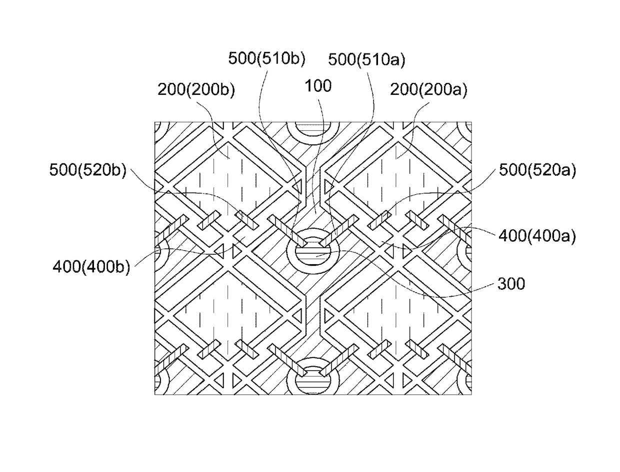
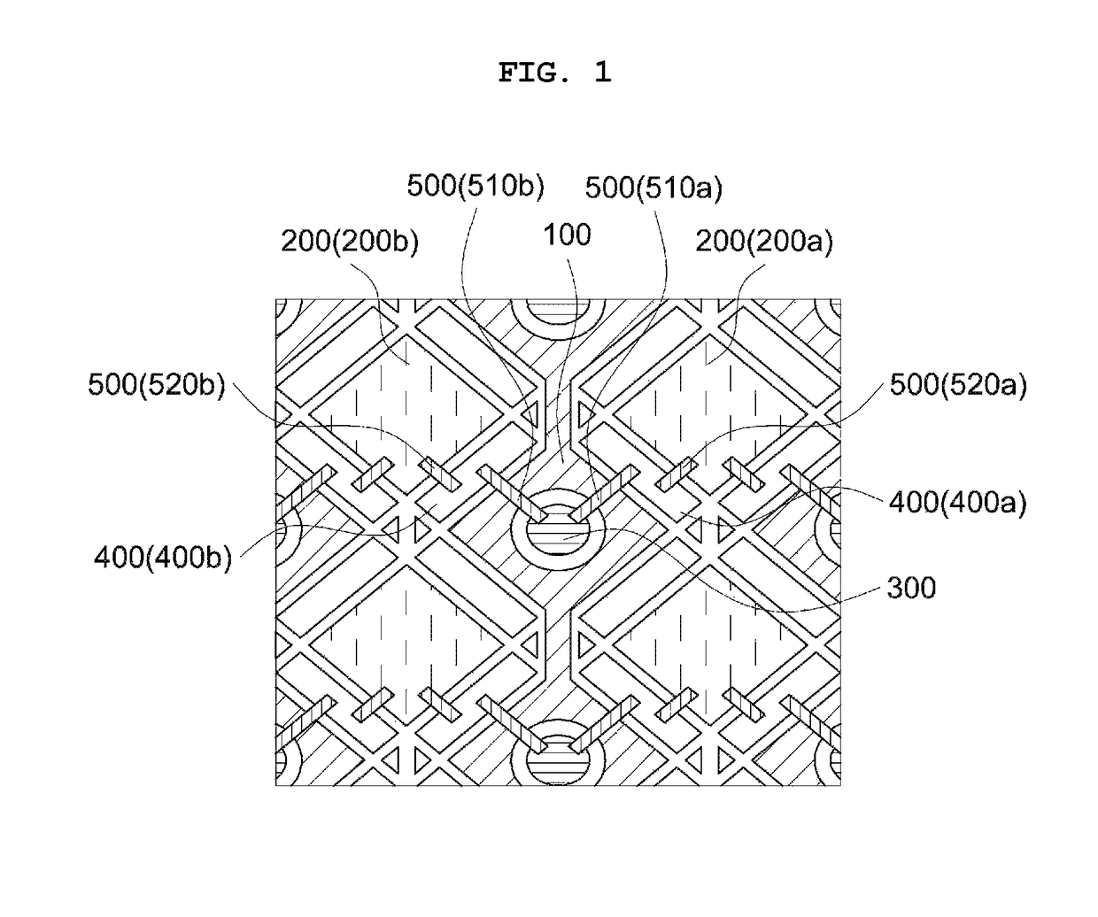
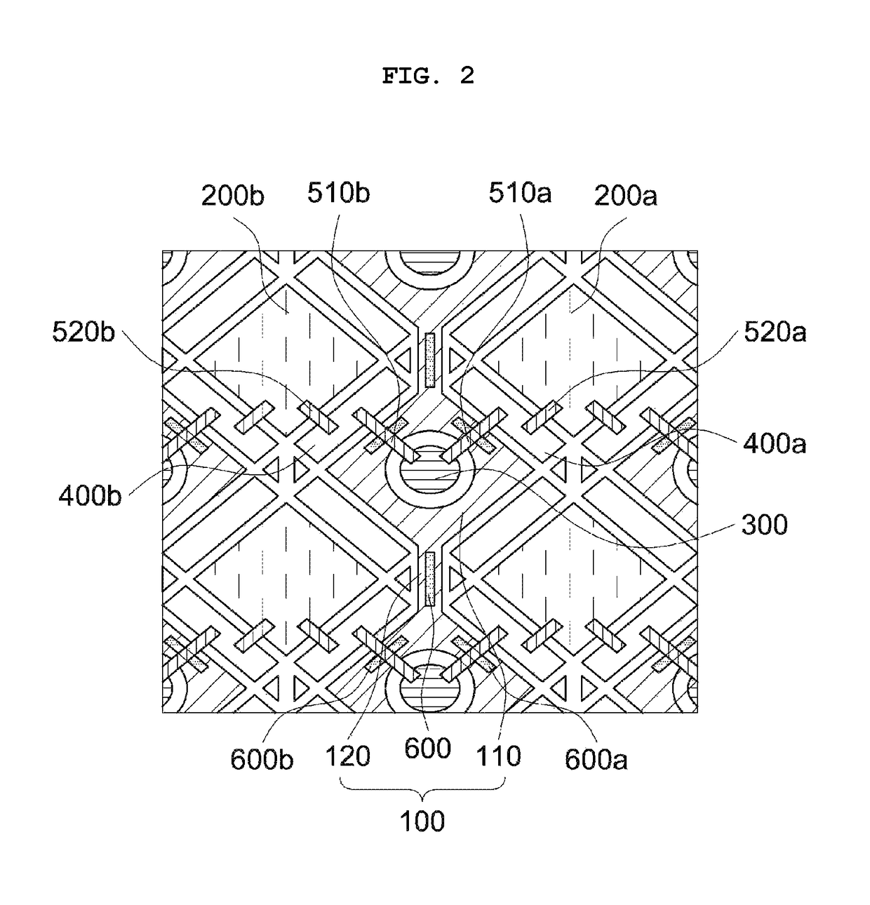
This patent describes a touch panel that has a reduced difference in resistance between touch sensing electrodes. This is achieved through a specific structure of relay and connection patterns that maintain electrical connection between the separated unit patterns of the touch sensing electrodes while reducing resistance deviation. Additionally, auxiliary electrode patterns are included to improve sensitivity and accuracy of the electrodes by equally or similar maintaining resistance between the first and second sensing patterns. The touch panel has also reduced visibility of the structure for electrically connecting the touch sensing electrodes, thereby reducing the impact on the displayed image.

Problems solved by technology

However, the electrode formed of the ITO, conductive polymer, or the like may have a high surface resistance, and a decrease in touch sensitivity and accuracy due to a difference in the surface resistance between the first pattern and the second pattern may be caused.
Korean Patent Laid-Open Publication No. 2013-0078065 discloses a touch panel including first patterns and second patterns which are formed on an upper surface and a lower surface of a transparent substrate, however, fails to suggest a solution in regard to the above-mentioned problems.

Method used


Image

  • Touch panel and image display device including the same
  • Touch panel and image display device including the same
  • Touch panel and image display device including the same

Examples


example 2

(2) Example 2

[0143]A touch panel was manufactured according to the same procedures as described in Example 1, except that an auxiliary electrode pattern was further formed on an intersection portion of the first sensing pattern and the first connection pattern using an Ag—Pd—Cu alloy (thickness 200 nm), and an insulation layer was interposed between the auxiliary electrode pattern and the first connection pattern so as to be insulated from each other.

example 3

(3) Example 3

[0144]A touch panel was manufactured according to the same procedures as described in Example 2, except that an auxiliary electrode pattern was further formed on a connection portion of the first sensing pattern.

example 4

(4) Example 4

[0145]A touch panel was manufactured according to the same procedures as described in Example 1, except that, as illustrated in FIG. 4, an auxiliary electrode pattern was formed in a dot pattern on the intersecting portion of the first sensing pattern and the first connection pattern intersect using an Ag—Pd—Cu alloy (thickness 200 nm). The first connection pattern and the auxiliary electrode pattern were simultaneously formed in the same process so that two dot patterns were separated.


PUM


Abstract

A touch panel comprises a substrate and a touch sensing electrode formed on at least one surface of the substrate. The touch sensing electrode includes a first sensing pattern formed in a first direction, a second sensing pattern formed in a second direction, a first relay pattern formed at an inside of the first sensing pattern in an island form, a second relay pattern formed between the first sensing pattern and the second sensing pattern, and a connection pattern which electrically connect separated unit patterns of the second sensing pattern via the first relay pattern and the second relay pattern. The connection pattern includes a first connection pattern which connects the first relay pattern and the second relay pattern, and a second connection pattern which connects the second relay pattern and the unit pattern of the second sensing pattern.

Description

CROSS REFERENCE TO RELATED APPLICATIONS AND CLAIM OF PRIORITY[0001]The application claims the benefit of Korean Patent Application No. 10-2015-0165530, filed on Nov. 25, 2015, at the Korean Intellectual Property Office, the disclosures of which are incorporated by reference herein in their entirety.BACKGROUND[0002]1. Field[0003]Embodiments of the present invention relates to a touch panel and an image display device including the same.[0004]2. Description of the Related Art[0005]A touch screen panel is a screen panel equipped with a specific input device adapted to receive position input generated by touching the screen panel with a finger of a user, or the like. Such a touch screen panel does not use a keyboard but has a configuration of multi-layer laminates in which, when the finger of the user or an object such as a touch pen touches a specific character or position displayed on a screen, the touch screen panel identifies the position and directly receives data input from the sc...

Claims


Application Information

Patent Timeline
Patent Type & Authority Patents(United States)
IPC IPC(8): G06F3/041G06F3/044
CPCG06F3/0416G06F3/044G06F2203/04112G06F2203/04103G06F2203/04111G06F3/0445G06F3/0446
Inventor CHOI, BYUNG JIN
Owner DONGWOO FINE CHEM CO LTD
Learn More