Liquid discharge head
a liquid discharge head and liquid technology, applied in the direction of printing, inking apparatus, etc., can solve the problems of liquid differing, difference in flow speed of liquid, increase in viscosity of liquid in the vicinity of the nozzle, etc., to reduce the resistance difference, lessen the difference in jet speed, and reduce the resistance. difference
- Summary
- Abstract
- Description
- Claims
- Application Information
AI Technical Summary
Benefits of technology
Problems solved by technology
Method used
Image
Examples
first embodiment
Liquid Discharge Apparatus
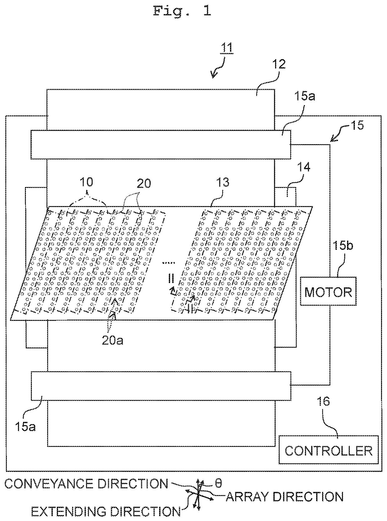
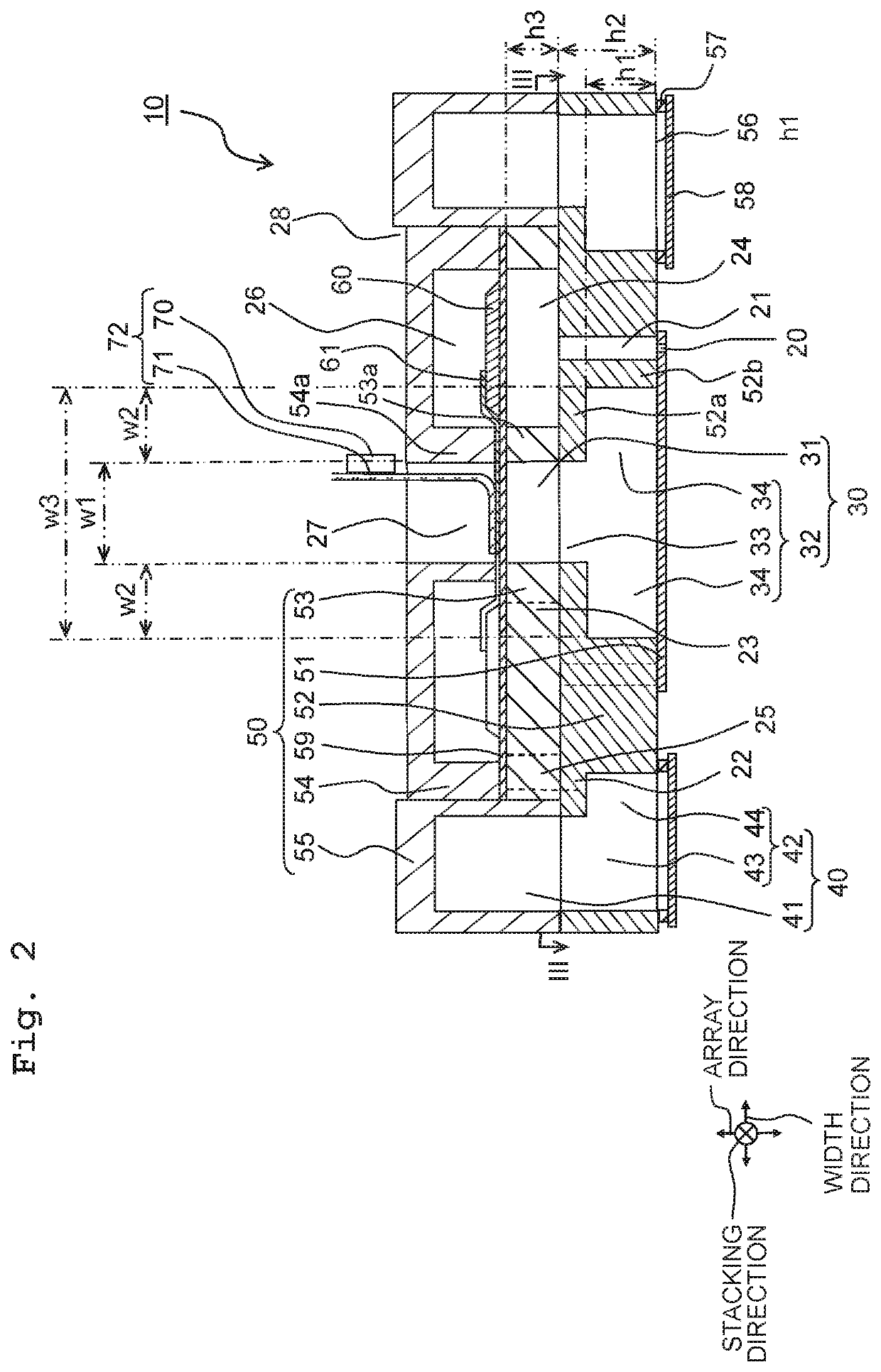
[0020]A liquid discharge apparatus 11 using heads 10 according to a first embodiment of the present disclosure is, as depicted in FIG. 1 for example, a printer carrying out printing on recording medium 12 with the liquid by way of jetting the liquid such as ink or the like while conveying the recording medium 12 such as printing paper or the like. Note that although the liquid discharge apparatus 11 will be explained below as an apparatus using the heads 10, apparatuses using the heads 10 are not limited to the above. Further, as the liquid discharge apparatus 11, a printer will be explained below, but the liquid discharge apparatus 11 is not limited to a printer as far as it is an apparatus that discharges liquid.
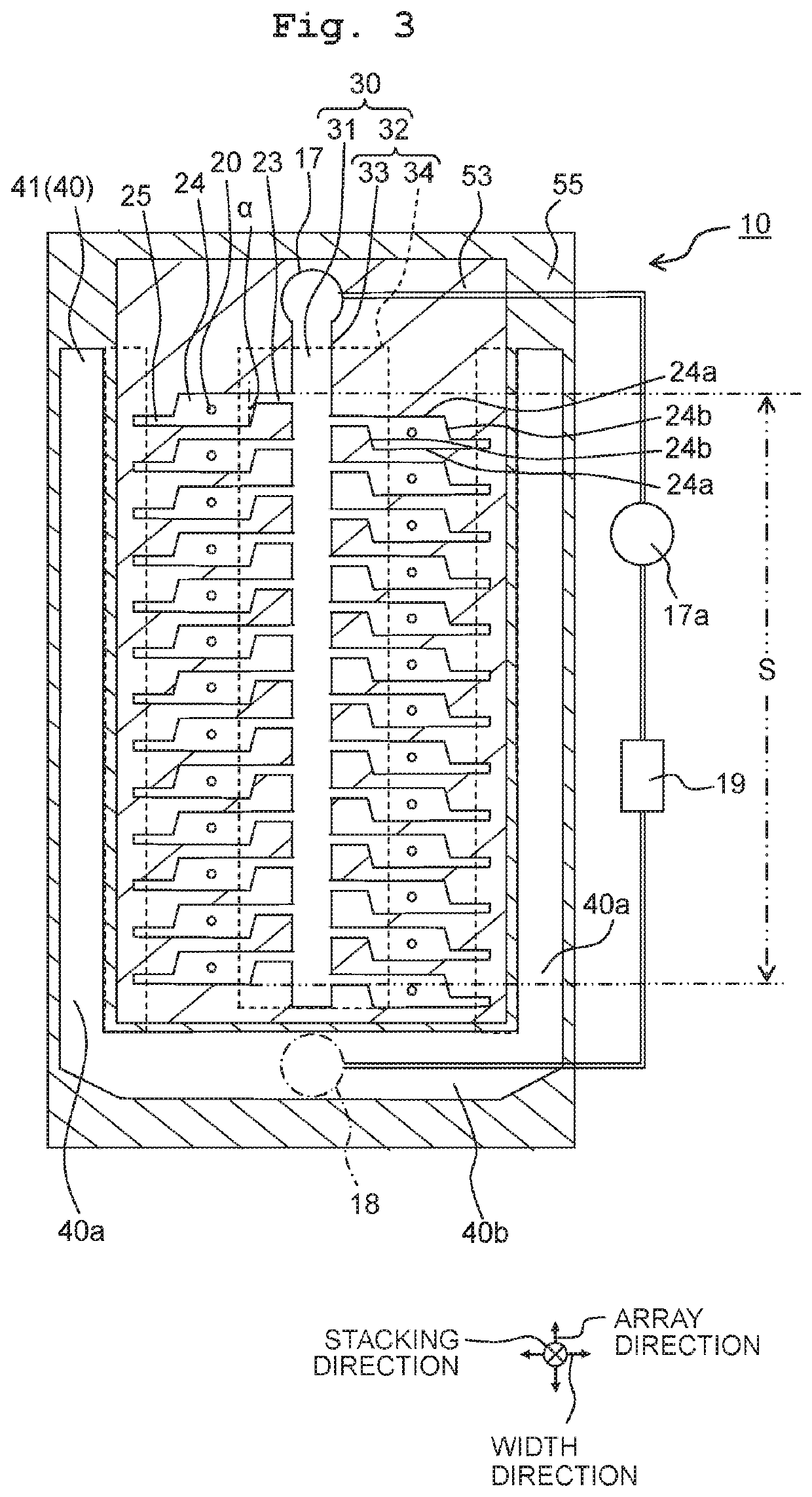
[0021]The liquid discharge apparatus 11 includes a head unit 13, a platen 14, a conveyance mechanism 15, and a controller 16. The head unit 13 has the plurality of heads 10, and the plurality of heads 10 are arranged to align in a direction orthog...
first modified embodiment
[0075]In a head 110 according to a first modified embodiment based on the first embodiment, as depicted in FIG. 4A, an expansion portion 134 of a second discharge portion 132 of a discharge common channel 130 has an angular portion 134c whose cross-sectional shape orthogonal to the array direction is curved. For example, the expansion portion 134 may have the angular portion 134c curved between a surface 134a intersecting the width direction and surfaces 134b intersecting the stacking direction.
[0076]For example, the expansion portion 134 is enclosed circumferentially in the communication plate 52 by a surface (the upper surface 134a) intersecting the stacking direction (being orthogonal thereto for example), a pair of surfaces (the lateral surfaces 134b) intersecting the width direction (being orthogonal thereto for example), and a pair of surfaces (the end surfaces) intersecting the array direction (being orthogonal thereto for example). The angular portion 134c between the upper ...
second modified embodiment
[0077]In a head 210 according to a second modified embodiment based on the first embodiment, as depicted in FIG. 4B, an expansion portion 234 of a second discharge portion 232 of a discharge common channel 230 has an angular portion 234c whose cross-sectional shape orthogonal to the array direction is inclined. For example, the expansion portion 234 may have the angular portion 234c inclined between a surface 234a intersecting the width direction and surfaces 234b intersecting the stacking direction.
[0078]For example, the expansion portion 234 is enclosed circumferentially in the communication plate 52 by an upper surface 234a, a pair of lateral surfaces 234b, and a pair of end surfaces. The angular portion 234c between the upper surface 234a and the lateral surfaces 234b is formed by an inclined surface chamfered into an oblique line inclined with respect to the upper surface 234a and the lateral surfaces 234b at a cross section along the array direction. Because the liquid smoothl...
PUM
 Abstract
Description
Claims
Application Information
 - R&D
- Intellectual Property
- Life Sciences
- Materials
- Tech Scout
- Unparalleled Data Quality
- Higher Quality Content
- 60% Fewer Hallucinations
Browse by: Latest US Patents, China's latest patents, Technical Efficacy Thesaurus, Application Domain, Technology Topic, Popular Technical Reports.
© 2025 PatSnap. All rights reserved.Legal|Privacy policy|Modern Slavery Act Transparency Statement|Sitemap|About US| Contact US: help@patsnap.com


