Blower with bearing tube

a technology of bearing tube and blower, which is applied in the direction of positive displacement liquid engine, piston pump, liquid fuel engine, etc., can solve the problems of compromising bearing performance, real world design is less than perfect, and the state of the art is far from per

Active Publication Date: 2008-12-11
RESMED MOTOR TECH
View PDF32 Cites 229 Cited by
  • Summary
  • Abstract
  • Description
  • Claims
  • Application Information

AI Technical Summary

Benefits of technology

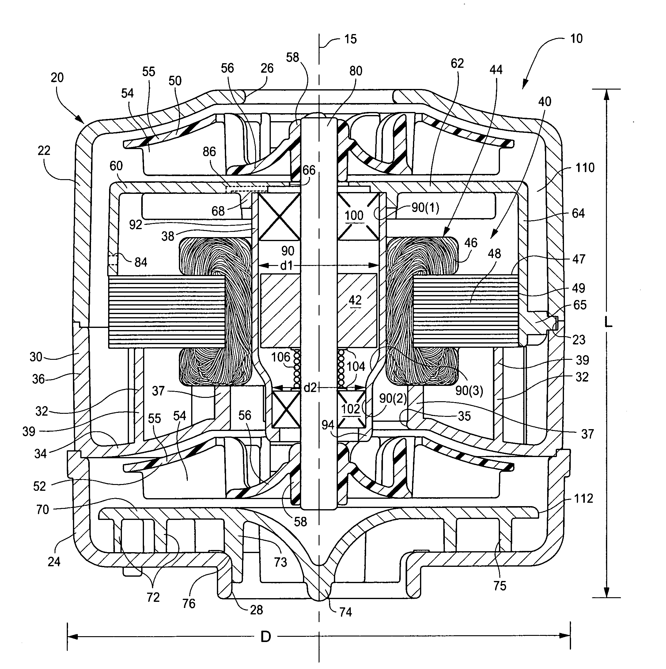
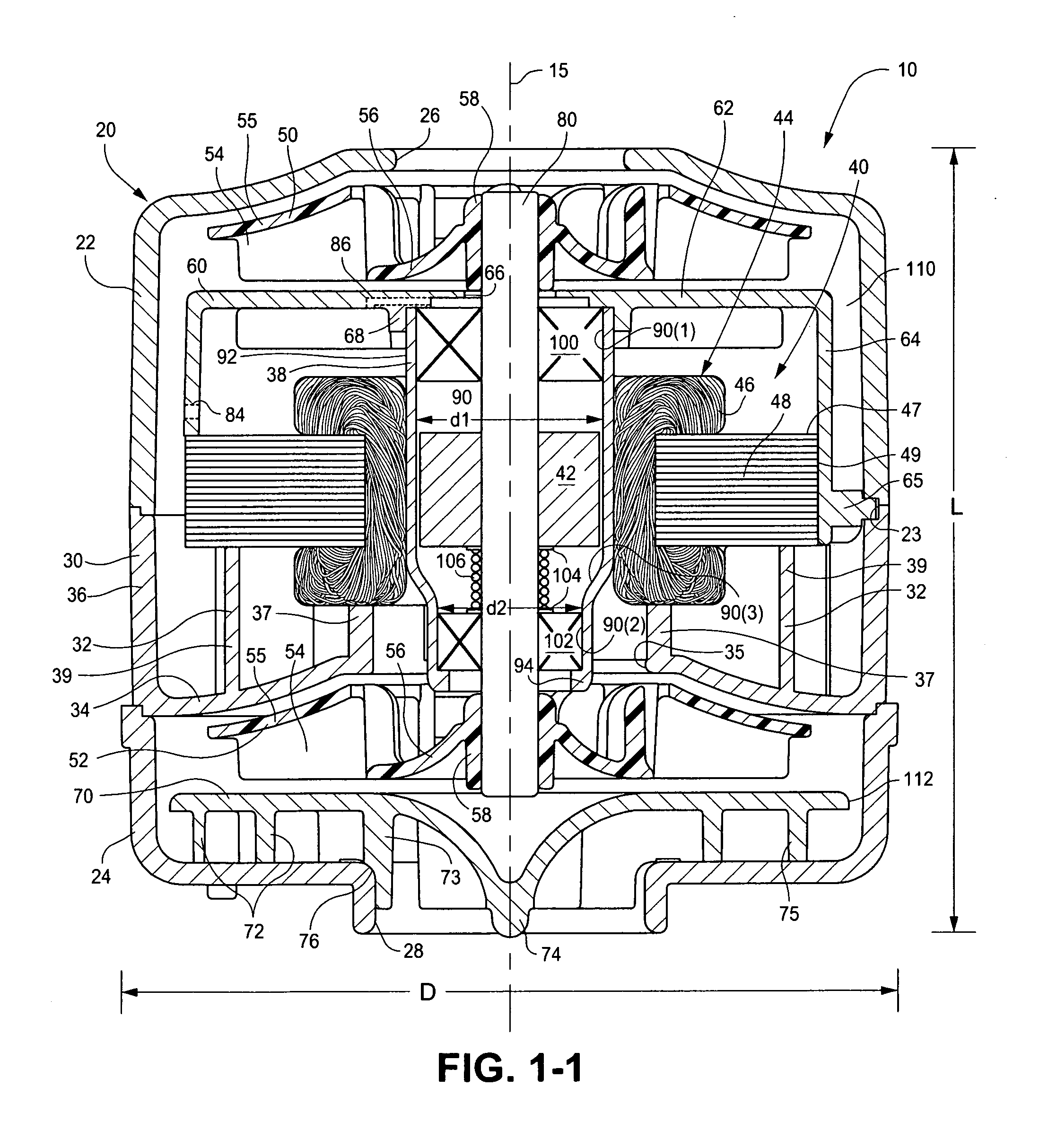
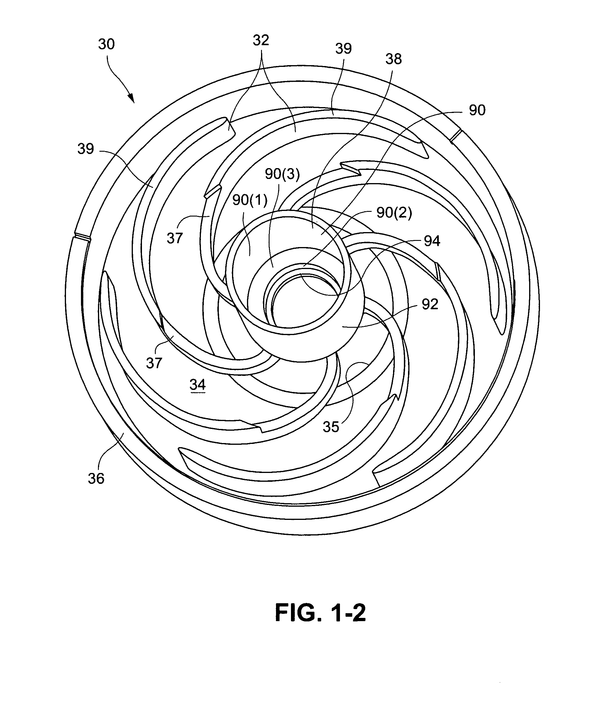
[0010]One aspect of the invention relates to a blower including a stationary portion including an inlet and an outlet, a rotating portion provided to the stationary portion (e.g., in close proximity to, but not touching), and a motor (e.g., electric motor) adapted to drive the rotating portion. The inlet and outlet are co-axially aligned. The stationary portion includes a housing, a stator component provided to the housing, and a tube providing an interior surface. The rotating portion includes one or more bearings that are provided along the interior surface of the tube to support a rotor within the tube (e.g., bearings connect the rotating portion to the stationary portion). In an alternative embodiment, the stator component may include stator vanes, and the stator vanes may be a separate part to the tube. In an embodiment, the blower is structured to supply air at positive pressure. In an embodiment, the stator component and / or tube may be constructed of a plastic material.

Problems solved by technology

Real world designs are less than perfect and, therefore, compromise bearing performance.
With respect to the first constraint, although the precision of part forming technologies improves continuously, the state of the art is far from perfect.
Furthermore, increased precision usually translates to greater expense, often dissuading a manufacturer from embracing the state of the art processes.
A consequence of multipart housings is that they accumulate unwanted tolerance build-up at each faying or joint surface, and, as such, each component part must be precisely shaped so that the accumulated dimensional errors remain within acceptable range.

Method used


Image

  • Blower with bearing tube
  • Blower with bearing tube
  • Blower with bearing tube

Examples


Embodiment Construction

[0052]The following description is provided in relation to several embodiments which may share common characteristics and features. It is to be understood that one or more features of any one embodiment may be combinable with one or more features of the other embodiments. In addition, any single feature or combination of features in any of the embodiments may constitute additional embodiments.

[0053]In this specification, the word “comprising” is to be understood in its “open” sense, that is, in the sense of “including”, and thus not limited to its “closed” sense, that is the sense of “consisting only of”. A corresponding meaning is to be attributed to the corresponding words “comprise”, “comprised” and “comprises” where they appear. Aspects of the invention will be described herein in its application to non-invasive ventilation (NIVV) treatment apparatus (e.g., positive airway pressure (PAP) devices or flow generators), such as CPAP (e.g., in the range of 4-28 cmH2O, at flow rates o...


PUM

PropertyMeasurementUnit
angleaaaaaaaaaa
lengthaaaaaaaaaa
lengthaaaaaaaaaa

Abstract

A blower includes a stationary portion including an inlet and an outlet, a rotating portion provided to the stationary portion, and a motor adapted to drive the rotating portion. The inlet and outlet are co-axially aligned. The stationary portion includes a housing, a stator component provided to the housing, and a tube providing an interior surface. The rotating portion includes one or more bearings that are provided along the interior surface of the tube to support a rotor within the tube. In an embodiment, the blower is structured to supply air at positive pressure.

Description

CROSS-REFERENCE TO APPLICATION[0001]This application claims the benefit of U.S. Provisional Application Nos. 60 / 924,909, filed Jun. 5, 2007, 60 / 996,001, filed Oct. 24, 2007, and 61 / 064,477, filed Mar. 7, 2008, each of which is incorporated herein by reference in its entirety.FIELD OF THE INVENTION[0002]The present invention relates to a blower for generating a pressure differential (e.g., air at positive or negative (vacuum) pressure). In an embodiment, the blower may be used in a positive airway pressure (PAP) device or flow generator used for the delivery of respiratory therapy to a patient. Examples of such therapies are Continuous Positive Airway Pressure (CPAP) treatment, Non-Invasive Positive Pressure Ventilation (NIPPV), and Variable Positive Airway Pressure (VPAP). The therapy is used for treatment of various respiratory conditions including Sleep Disordered Breathing (SDB) and more particularly Obstructive Sleep Apnea (OSA). However, the blower may be used in other applicat...

Claims


Application Information

Patent Timeline
Patent Type & Authority Applications(United States)
IPC IPC(8): F04D29/046F04D25/06
CPCH02K5/128H02K7/083H02K1/185H02K5/225F04D25/082H02K7/14H02K5/1732Y10T29/49009A61M2205/3368H02K5/08F04D25/0606H02K15/0435A61M16/122H02K9/14H02K5/24A61M16/0066H02K2205/09F04D29/059A61M2202/0208F04D25/12A61M2205/42H02K3/522H02K2213/03F04D29/601F04D29/668F04D29/083F04D25/08F04D29/663F04D29/5806F04D29/403F04D25/0646
Inventor KENYON, BARTON JOHNSEARS, DAVID B.NAGORNY, ALEKSANDRMEBASSER, SAMUEL AZIZSWEENEY, PETER JOHN
Owner RESMED MOTOR TECH
Why Eureka
Try Eureka