Hinge

a technology of hinge and lateral adjustment, which is applied in the field of hinge, can solve the problems of complicated operation, time-consuming, and use of tools, and achieve the effect of simple and reliable lateral adjustmen

Inactive Publication Date: 2008-12-18
ASSA ABLOY AB
View PDF12 Cites 40 Cited by
  • Summary
  • Abstract
  • Description
  • Claims
  • Application Information

AI Technical Summary

Benefits of technology

[0012]One object of the present invention is thus to make available a hinge which, at one and the same time, permits the simple and reliable lateral adjustment of a door attached to the hinge, in a direction perpendicular to the axis of the hinge and parallel to the plane of the door, and the simple attachment and removal of the door respectively to and from the door frame.

Problems solved by technology

In practice, however, this involves a complicated operation, because both an upper and a lower adjusting screw must be actuated in conjunction with adjustment.
Such removal and corresponding attachment of the hinge leaf requires the use of tools and is also complicated and time-consuming.
Such free play has a detrimental effect on the satisfactory attachment and fixing of the door part leaf to the holding box.
It is not possible with this hinge, however, to obtain any lateral adjustment of the door, perpendicular to the axis of the hinge and parallel to the plane of the door.
Previously disclosed hinges thus do not offer both satisfactory and simple attachment and removal of the hinge leaf respectively to and from the holding box as a possibility for providing lateral adjustment of the door.

Method used


Image

  • Hinge
  • Hinge
  • Hinge

Examples


Embodiment Construction

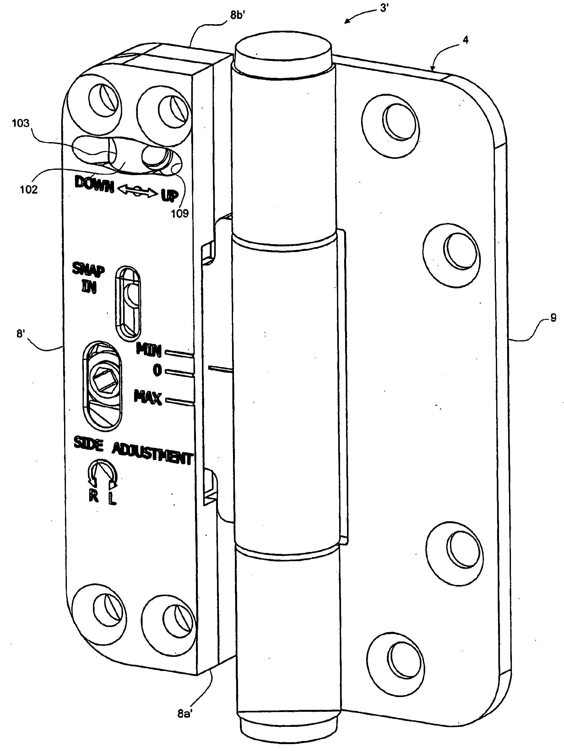
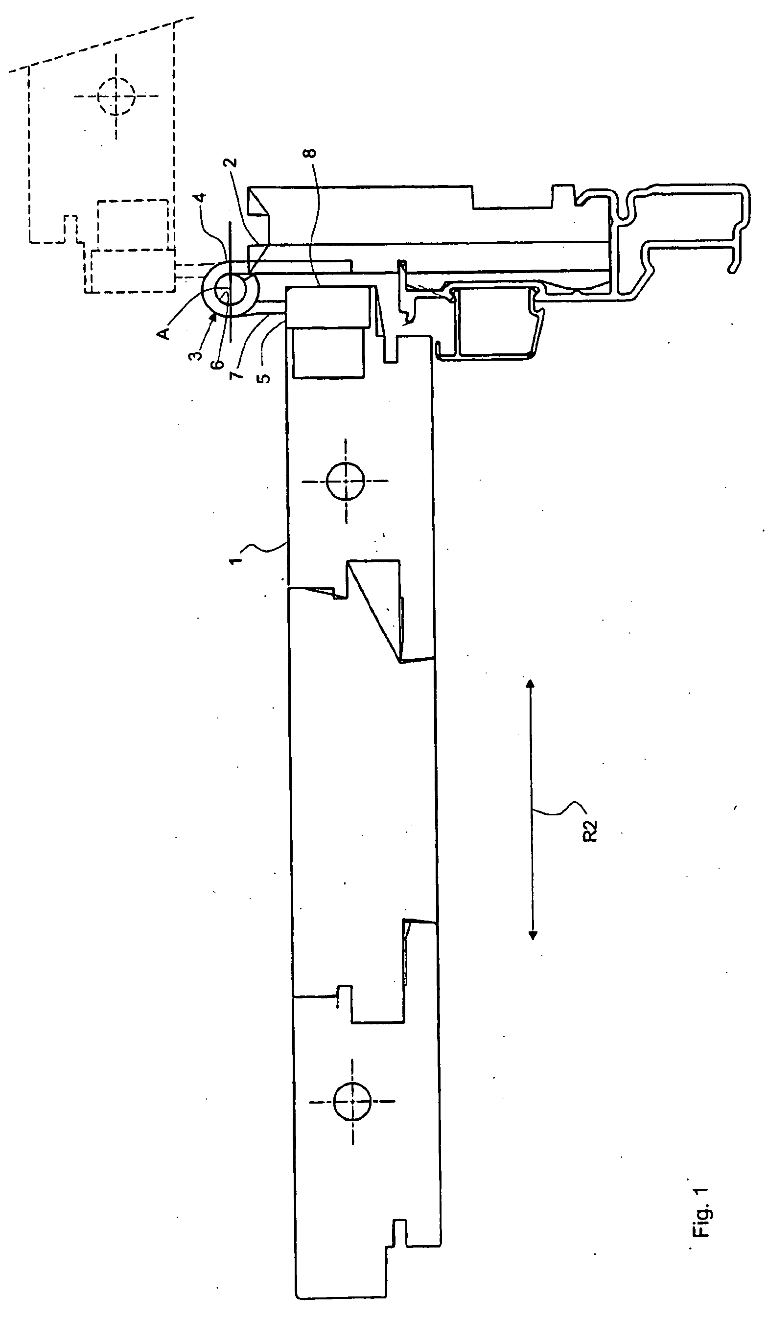
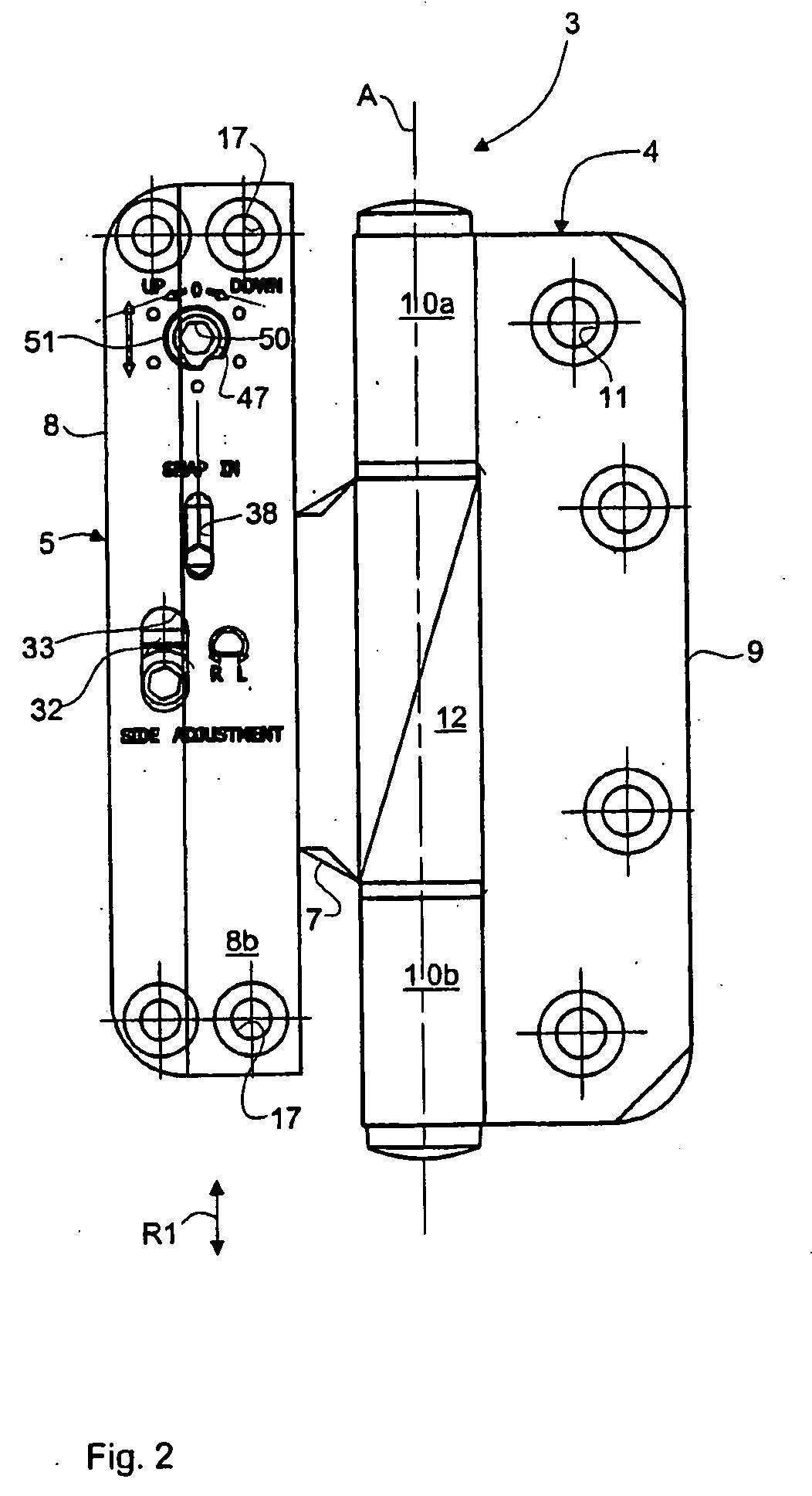
[0037]Illustrated in FIG. 1 is a door 1 that is attached to a frame 2 by means of a hinge 3 in accordance with the invention. In the Figure the door is shown in the closed position by an unbroken line and in the open position by a broken line. The hinge 3 comprises a frame part 4 and a door part 5, each of which exhibits a knuckle which surrounds a hinge pin 6 in the customary fashion. The central axis of the hinge pin 6, about which the door part 5 and thus the door 1 can pivot relative to the frame 2, defines a hinge axis A. The door part 5 also comprises a hinge leaf, namely a door part leaf 7 and a holding box 8, in which the door part leaf is accommodated and is snapped securely into engagement. The holding box 8 is attached in a previously disclosed fashion by means of screws to the door 1 in a recess provided for the purpose. The holding box 8 exhibits an opening 19 (FIG. 3) or a lateral recess for the introduction of the door part leaf 7. As can be appreciated from the Figur...


PUM


Abstract

A hinge (3, 3′) with a frame part (4, 204) and a door part (5), which door part exhibits a holding box (8, 8′) for installation on a door (1) or equivalent, and a hinge leaf (7, 207) that is detachably attachable to the box, which box comprises a lateral recess (19) for the hinge leaf, and a receiving part (20, 20′, 220) for the hinge leaf present inside the box. In order to permit the simple and reliable lateral adjustment of the door and its simple installation and removal and the positive fixing of the position of the hinge leaf in the receiving part, the box (8, 8′) is capable of being caused to move relative to the receiving part (20, 20′) by the actuation from the outside of an adjustment device (32) for the purpose of providing lateral adjustment of the box and the door in the plane of the door, perpendicular to the axis (A) of the hinge, and the hinge comprises a spring-actuated snap element (39, 239) for the detachable attachment of the position of the hinge leaf (7, 207) in the receiving part.

Description

[0001]The present invention relates to a hinge with a holding box for accommodating a hinge leaf, and more specifically of the kind indicated in the preamble to claim 1.[0002]Hinges of the indicated kind—which permit simple installation and removal can find application on different types of doors, windows, hatch covers and other hinged elements.[0003]In order to permit adjustment of the hinged element in relation to the frame with its side pieces, lintel and sill, the hinge can be provided with means for adjustment in the vertical, closing and / or lateral direction.[0004]In the case of a holding box of the kind in question, in particular for a door, the requirement is often imposed that it must be made of a fire-retardant material, so that the door remains in its closed position for as long as possible in the event of a fire.[0005]In the case of other types of holding boxes for simpler purposes, one or more of the component parts of the holding box can consist of plastic, for example...

Claims


Application Information

Patent Timeline
Patent Type & Authority Applications(United States)
IPC IPC(8): E05D7/04
CPCE05D7/0415E05D7/0423E05D2003/025E05D2007/0461E05D2007/0469E05D2007/0476Y10T16/5324E05Y2400/818E05F15/00E05Y2900/132Y10T16/53247Y10T16/53253E05D2007/0484
Inventor KARLSSON, BENNY
Owner ASSA ABLOY AB
Why Eureka
Try Eureka