Adjustable support assembly

a technology of supporting assembly and adjustable structure, which is applied in the direction of machine supports, manufacturing tools, washstands, etc., can solve the problems of frequent attention and rendered their use less than fully convenient, and achieve the effect of simple and reliable tools and effectively solving tedious and cumbersome tasks

Inactive Publication Date: 2006-11-28
HEATON KENNETH
View PDF2 Cites 21 Cited by
  • Summary
  • Abstract
  • Description
  • Claims
  • Application Information

AI Technical Summary

Benefits of technology

[0011]Yet other objects of the invention are to provide an installation support which is adaptable to various configurations and is easily manipulated for proper alignment.
[0012]Briefly these and other objects are accomplished within the present invention by providing a generally planar base surface conformed to threadably engage one end of a pipe segment aligned in a generally orthogonal projection therefrom. The free end of the segment is both finished to form a smooth bearing surface and is further fixed to the upper end of an exterior longitudinal channel to provide a radial recess extending longitudinally along the exterior surface of the segment. A selected one of a complement of various length threaded rods first threaded through the interior of a nut assembly is then inserted into the segment such that the extending portion thereof is then receivable within the upper opening of the segment with the nut assembly supported on the surrounding bearing surface. In this manner rotary advancement of the nut assembly raises and lowers the free projecting end of the inserted rod which may be threadably secured to one of several adaptor fixtures conformed in a first embodiment to mate with a corresponding bottom structure of a disposal that is being installed and in the second embodiment to a supporting cradle for other articles. To prevent the adaptor-rod combination from turning with the nut assembly as it is rotated a threaded sleeve mounted on the rod is locked by compression against the adaptor to deploy a longitudinal bar along the rod exterior into the recess in the channel along the pipe segment.
[0013]Those skilled in the art will further appreciate that the foregoing combination is easily conformed to various sink cabinet, disposal geometries and other structures. In each instance, moreover, the thread pitch of the nut assembly and weight of the supported article are combined with the contact dimensions of the base plate to preclude the rotary movement thereof as the article is raised. The plumber engaged in the replacement or other installation task thus needs only one hand to manipulate the nut assembly leaving the other hand free for fitting alignments obtained by a simple and reliable tool that effectively resolves a tedious and cumbersome task.

Problems solved by technology

While many improvements have made to render these devices and their plumbing quite reliable, the complex nature of the mechanism and the frequency of its use and abuse make it an item of frequent attention.
Most often this attention requires removal and replacement, or re-installation following repair, of the device to the underside of the sink drain opening, a task requiring manipulation of a fairly heavy and cumbersome article within the narrow and crowded confines of the cavity under the sink.
This distant adjustment facility of these prior art devices has rendered their use less than fully convenient.

Method used


Image

  • Adjustable support assembly
  • Adjustable support assembly
  • Adjustable support assembly

Examples


Embodiment Construction

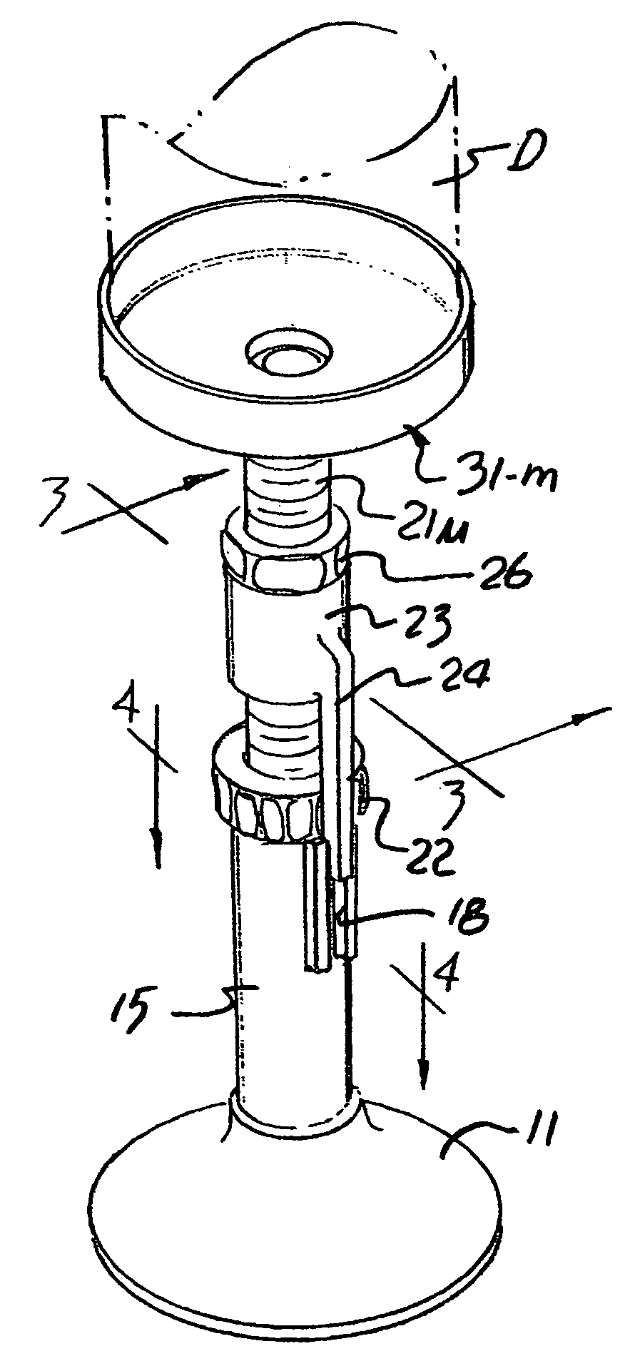
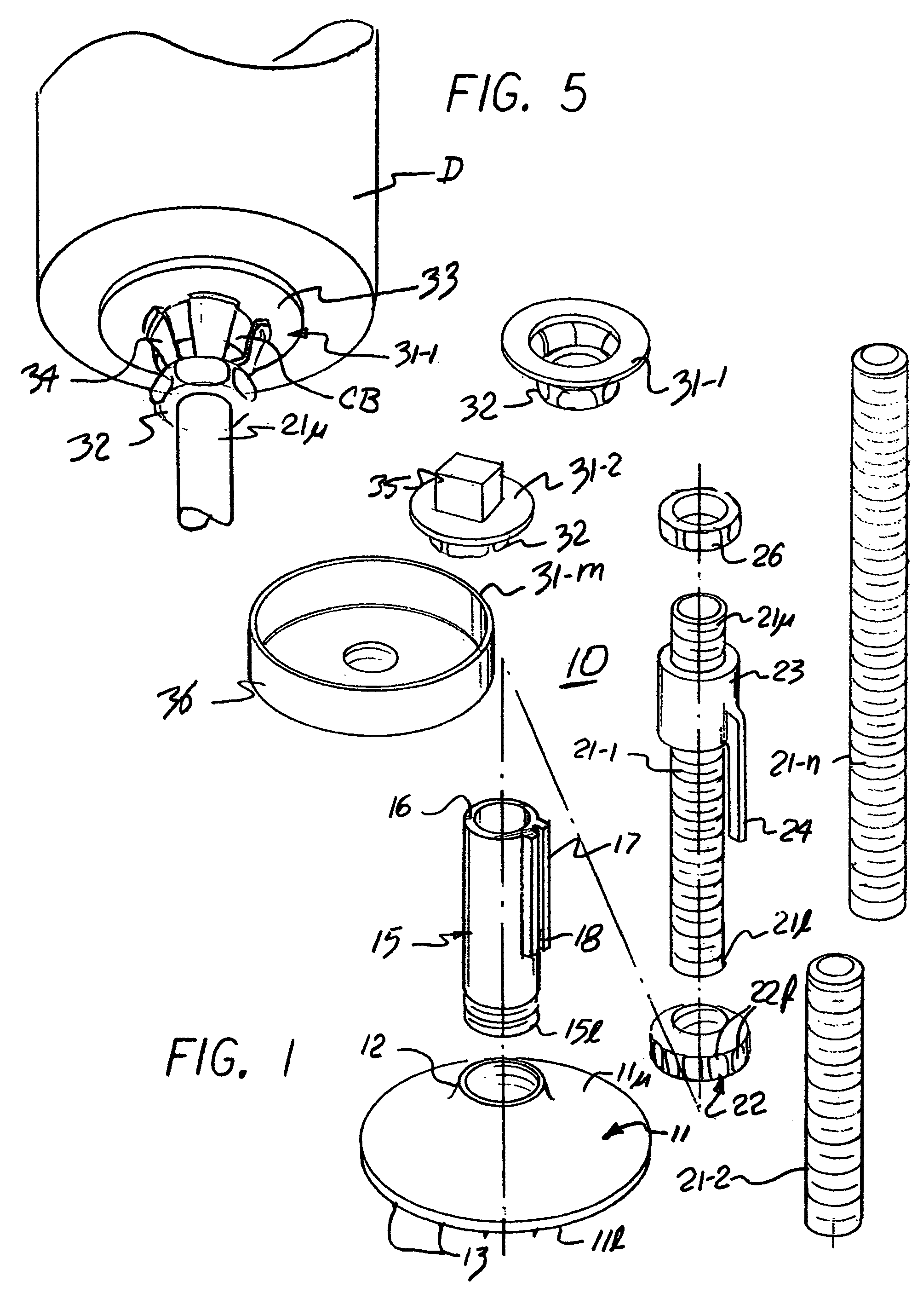
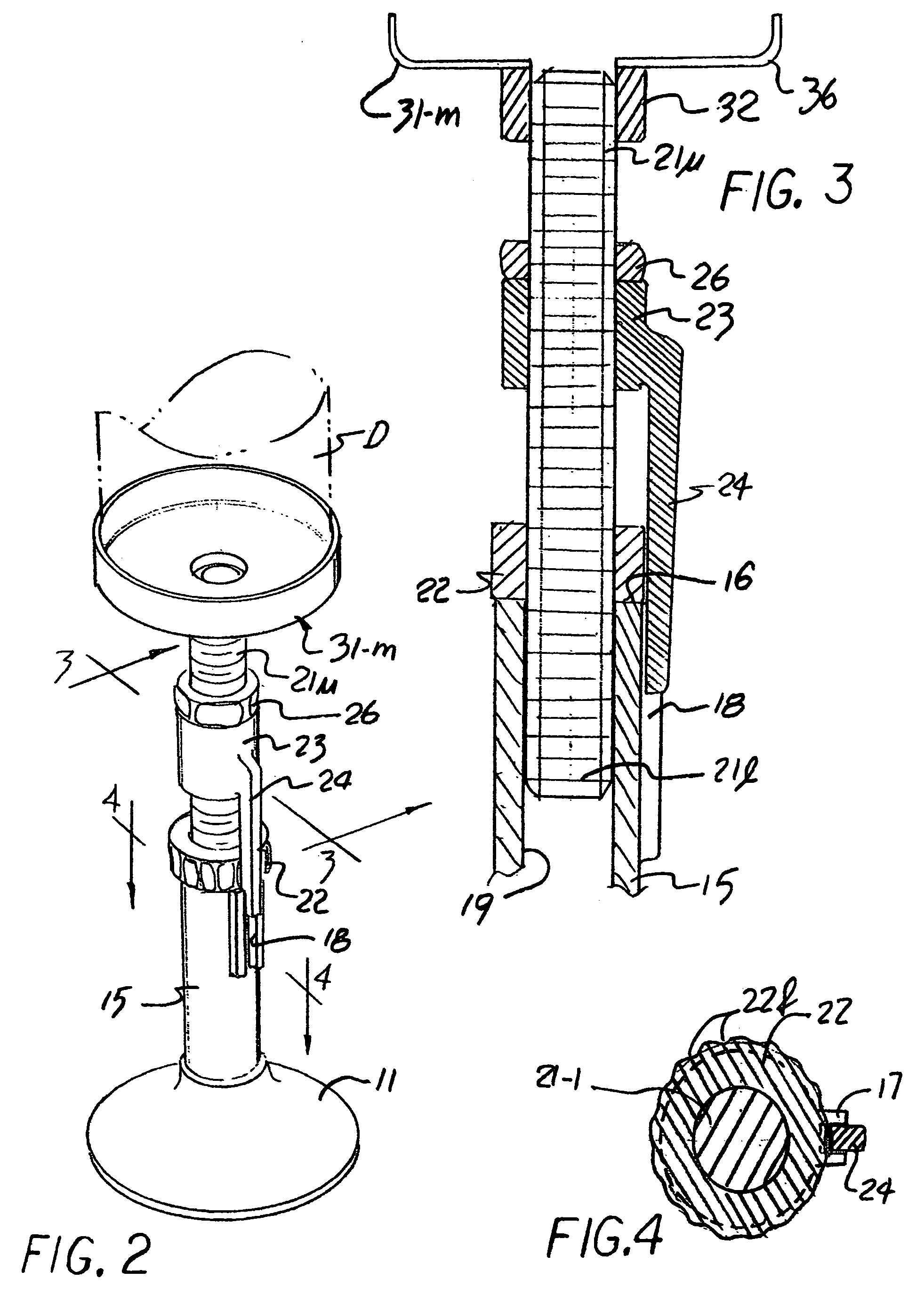
[0021]As shown in FIGS. 1–4, the inventive support assembly, generally designated by the numeral 10, comprises a base 11 of a generally planar configuration provided with a threaded boss 12 on the upper surface 11u thereof. The peripheral edge surface of the lower surface 11l may be finished to a rough finish, shown by projections 13, to increase frictional resistance to any rotary displacement thereof A pipe segment 15 exteriorly threaded over the lower end surface 15l is then threadably insertable into the boss 12 to form a vertically aligned annular structure supported on the base and defined at the upper end 15u by a smoothed end surface 16. A longitudinally aligned channel piece 17 is then affixed to the outer surface of segment 15 to present a radially directed recess 18 extending from surface 16 along a portion of segment 15.

[0022]A selected one of a plurality of threaded rods 21-1 through 21-n, shown as rod 21-1 in the Figure, is then threadably received in the interior of a...


PUM

PropertyMeasurementUnit
lengthsaaaaaaaaaa
electromechanical structureaaaaaaaaaa
frequencyaaaaaaaaaa

Abstract

A support assembly useful in supporting a plumbing fixture in the course of effecting connections thereto includes a base provided with a vertical tube segment supporting a nut assembly threadably engaged to a rod partly received in the segment with the upper rod end supporting an adapter conformed to the supported fixture. An offset bar fixed to the rod exterior engages a lateral recess on the segment to fix the rod in rotation as the nut assembly is turned. The assembly may include rods of differing lengths and adapters of various forms.

Description

REFERENCE TO RELATED APPLICATIONS[0001]This application is a continuation-in-part of U.S. patent application Ser. No. 10 / 843,602 filed on May 11, 2004 now U.S. Pat. No. 7,024,743 and the benefit of this earlier filing date is claimed for all matter common with this parent application.BACKGROUND OF THE INVENTION[0002]1. Field of the Invention[0003]The present invention relates to tools useful in plumbing assembly, and more particularly to manually adjustable structures insertable under the free edges of a cantilevered sinks and the like while plumbing connections are effected to the drain openings thereof.[0004]2. Description of the Prior Art[0005]The plumbing connection below a sink often include complex geometries confined in a small space that are sometimes compounded by items like a food debris macerators, or garbage disposal, in current implementation comprises an electromechanical structure of some bulk and mass. While many improvements have made to render these devices and the...

Claims


Application Information

Patent Timeline
Patent Type & Authority Patents(United States)
IPC IPC(8): B66F3/08A47F5/00B23P19/04A47K1/14E03C1/266
CPCE03C1/2665Y10T29/53913Y10T29/53848Y10T29/53891
Inventor HEATON, KENNETH
Owner HEATON KENNETH
Why Eureka
Try Eureka