System and method for controlling a compressor

a compressor and speed control technology, applied in the direction of positive displacement liquid engines, lighting and heating apparatus, instruments, etc., can solve the problems of system operating inefficiency, inefficient climate system at meeting some cooling demands, etc., and achieve the effect of optimizing the compressor

Active Publication Date: 2008-12-18
FORD GLOBAL TECH LLC
View PDF18 Cites 13 Cited by
  • Summary
  • Abstract
  • Description
  • Claims
  • Application Information

AI Technical Summary

Benefits of technology

This invention describes a control system for a compressor used in a climate system. It includes two parts: a first part that controls the compressor based on its current temperature and a desired temperature, and a second part that controls the compressor based on the pressure of the climate system. By combining these two signals along with pre-defined data about optimum compressor speeds, the control system can ensure that the compressor runs at the best possible speed for efficient operation.

Problems solved by technology

The technical problem addressed by this patent is the inefficiency of traditional climate systems due to their fixed compressor speeds which can only meet certain cooling needs, resulting in energy wastage during operation.

Method used


Image

  • System and method for controlling a compressor
  • System and method for controlling a compressor
  • System and method for controlling a compressor

Examples


Embodiment Construction

)

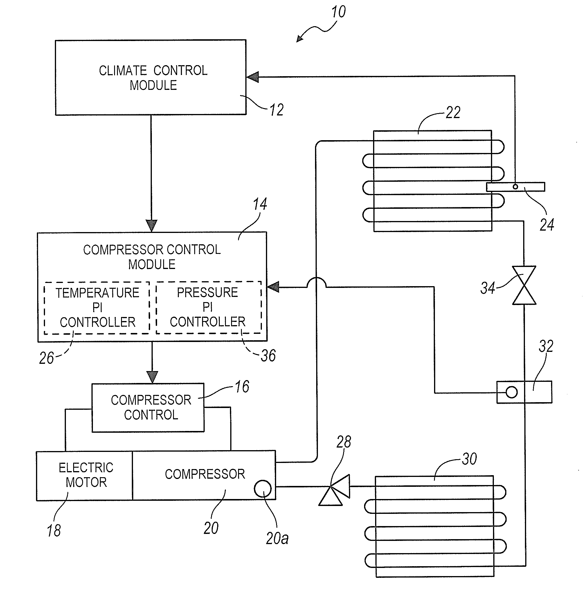
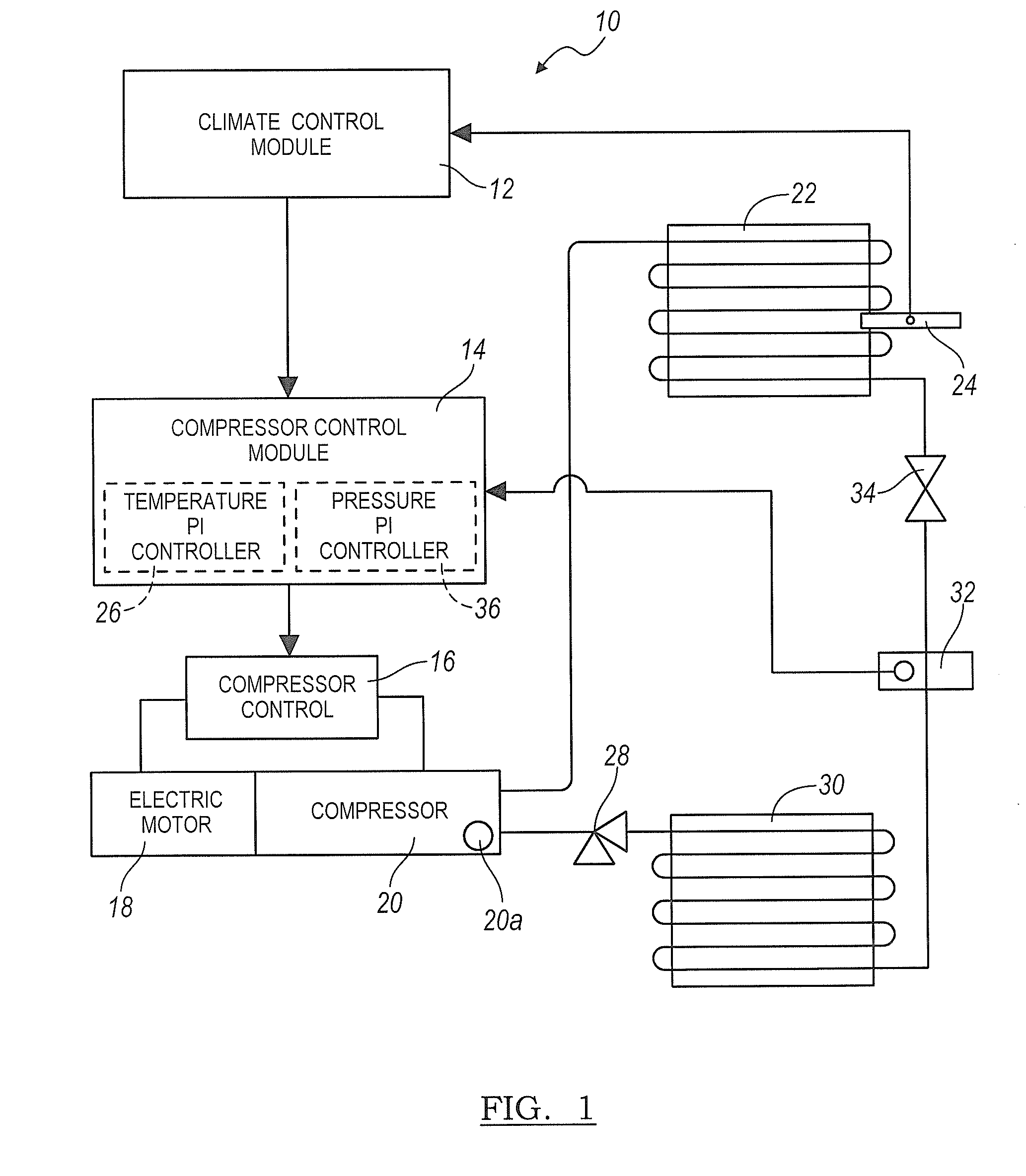
[0012]Referring to FIG. 1, a climate system 10 is shown that efficiently provides target cooling in response to cooling demands. Climate system 10 may be installed in a vehicle. It is recognized, however, that climate system 10 may be equally adapted for non-vehicular applications (e.g., buildings, homes, etc.). As shown, climate system 10 includes a climate control module 12, a compressor control module 14, an electric motor 18, compressor controls 16, a compressor 20, an evaporator 22, a pressure relief valve 28, a condenser 30, a transducer 32, a thermal expansion valve (TXV) 34, and a temperature sensor 24. It is recognized that some embodiments may have more or less devices than those shown in FIG. 1 without departing from the scope of the present invention.

[0013]Climate control module 12 and compressor control module 14 either individually or in combination may function as a controller device that processes signals received from various devices within climate system 10 to eff...


PUM


Abstract

The embodiments described herein include a control system and method for a compressor that is operable with a climate system. The control system enables optimal climate system operation by efficiently controlling the operating speed of the compressor.

Description


Claims


Application Information

Patent Timeline
Owner FORD GLOBAL TECH LLC
Why Eureka
Try Eureka