
Lighting System and a Method For Controlling a Lighting System

a lighting system and lighting technology, applied in the direction of lighting apparatus, light sources, instruments, etc., can solve the problem of not being able to explain how to actually perform the determination of topology

Inactive Publication Date: 2008-12-18
SIGNIFY HLDG BV
View PDF12 Cites 43 Cited by
  • Summary
  • Abstract
  • Description
  • Claims
  • Application Information

AI Technical Summary

Benefits of technology

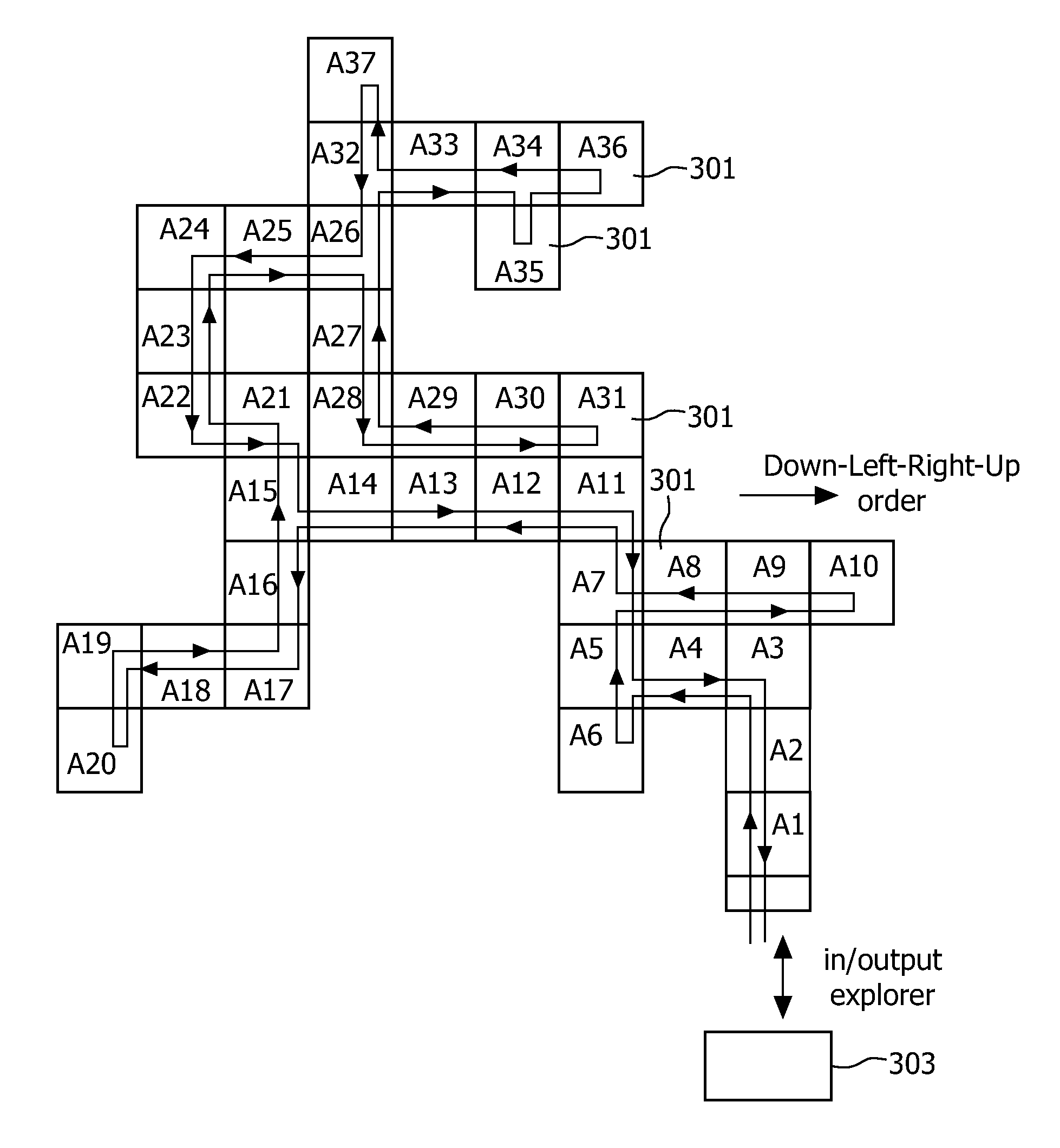
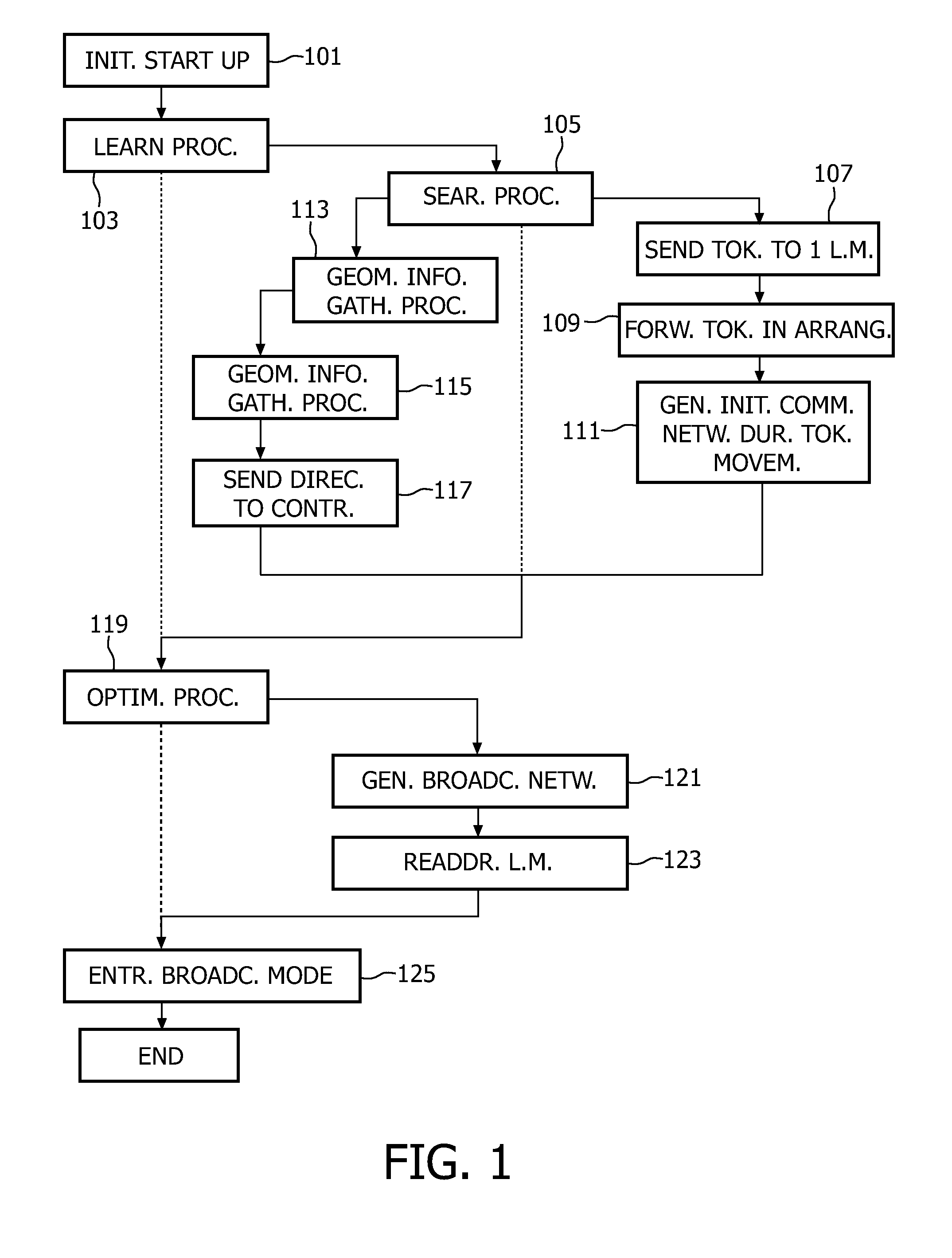
The present invention provides a method and system for controlling a lighting system that overcomes the limitations of prior art. The method involves detecting the arrangement of lighting modules in a geometrical cluster and providing a self-configuration system where the controlling device has knowledge about the size and shape of the cluster. The lighting modules are able to communicate with each other and the controlling device via communication units at several sides. The method includes a learning procedure for defining the lighting module arrangement and the communication network, and the use of a token that is circulated among the lighting modules to obtain geometric information. The lighting modules have internal orientation synchronization and can be rotated when assembled. The method also includes an optimization procedure to generate an optimized data path through the lighting module arrangement. The lighting system includes a plurality of polygonal lighting modules and a controlling device that can communicate with each other, and the lighting modules can be arranged in an arbitrary manner. The system also includes communication units at several sides of the lighting modules, and the lighting modules can be set in an idle state ready to receive communication from any side. The knowledge about the lighting module arrangement is used for the optimization. The invention provides a more efficient and flexible lighting system.

Problems solved by technology

One particular problem is how to make the lighting system as free as possible when it comes to how to arrange the lighting modules.
Thus, there is no complete explanation of how to actually perform the determination of the topology, i.e. the size and shape of the arrangement of lighting modules.

Method used


Image

  • Lighting System and a Method For Controlling a Lighting System
  • Lighting System and a Method For Controlling a Lighting System
  • Lighting System and a Method For Controlling a Lighting System

Examples


Embodiment Construction

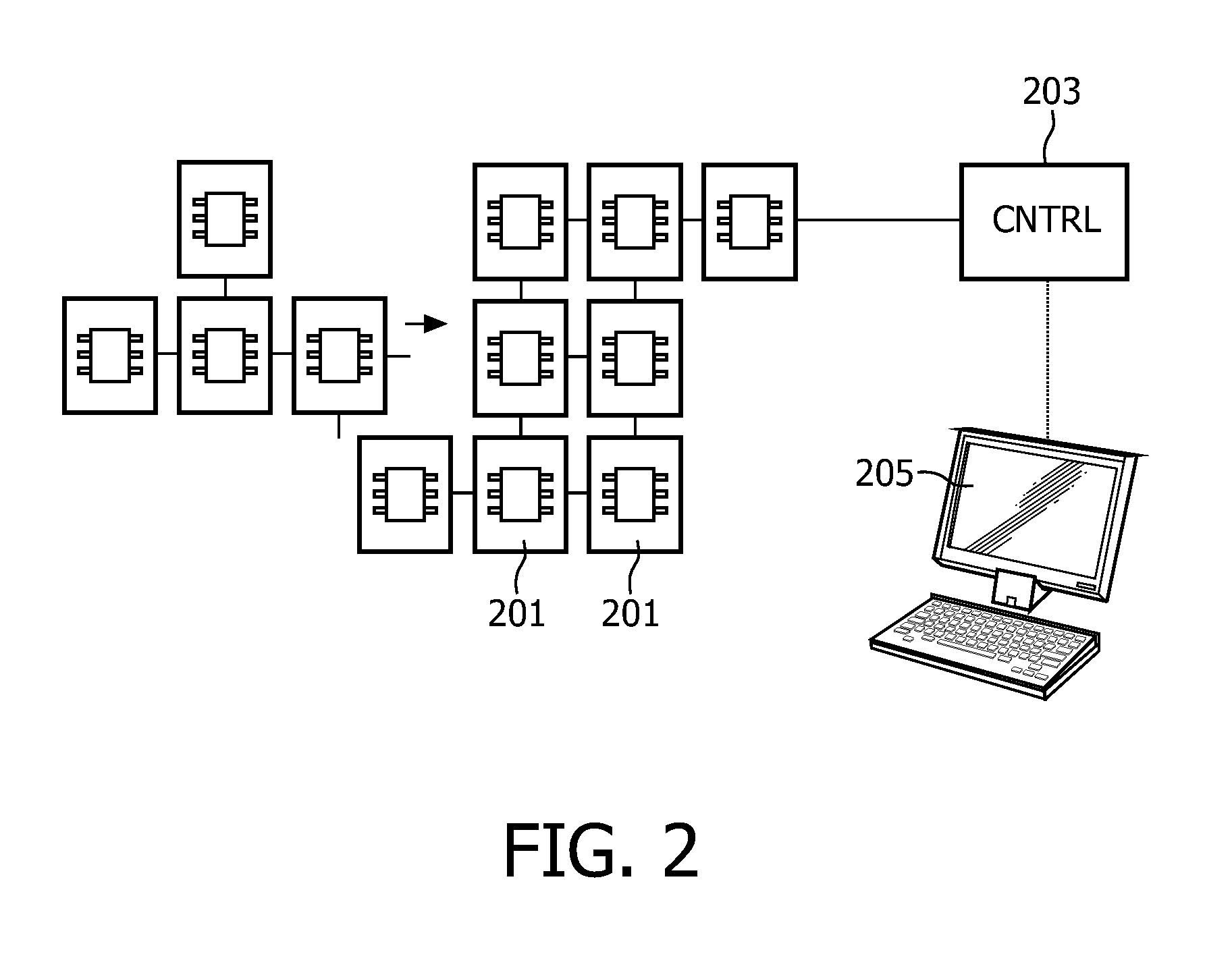
[0033]Referring to FIG. 2 a lighting system comprises several lighting modules 201, a controlling device 203, and a PC (Personal Computer) 205. Each lighting module 201 contains one or more light sources, as shown in FIG. 7. The lighting modules 201 are polygonal. For example, they are rectangular in FIG. 2 and square in FIG. 3. For purposes of simplicity only two-dimensional arrangements of thin lighting modules, or tiles, 201 are shown in this application, while three-dimensional arrangements are possible as well. As shown in FIG. 6, the lighting modules 601 are able to communicate with each other by means of communication units 603. In the embodiment as shown, the communication units of each lighting module 601 are located one at each side of the lighting module 601. Consequently, in the embodiments shown the lighting modules 201, 601 are able to communicate with four neighboring lighting modules 201, 601. However, the number of neighbors can vary from one to four.

[0034]The light...


PUM


Abstract

This invention relates to method of controlling a lighting system including a plurality of polygonal lighting modules and a controlling device, which are able to communicate with each other. The lighting modules are arbitrarily arrange able, since each lighting module is able to communicate with neighboring lighting modules via communication units arranged at several sides of the lighting module. The method includes a learning procedure for defining a lighting module arrangement and a communication network for communication between the controlling device and the lighting modules. During the learning procedure a token is forwarded from lighting module to lighting module, while ensuring that all lighting modules are visited by the token; and geometric information about how the lighting modules are arranged in relation to each other is generated.

Description

FIELD OF THE INVENTION[0001]The present invention relates to a method for controlling a lighting system, which is built-up from polygonal lighting modules and a controlling device, and to such a system.BACKGROUND OF THE INVENTION[0002]Lighting systems of the kind referred to here generally consist of polygonal lighting modules, i.e. light emitting modules, which are arranged to form an arrangement of a desired shape and size. For example, walls are fully or partly covered with a lighting module arrangement for displaying large images, or three-dimensional structures are formed for aesthetic applications.[0003]One lighting system is disclosed in published US patent application No. 2005 / 0116667 A1. In that prior art system the lighting modules are thin building blocks called tiles, and each lighting module has several communication units, or ports, which are located one at each side of the lighting module. The lighting modules are arranged in a network for communication between the co...

Claims


Application Information

Patent Timeline
Patent Type & Authority Applications(United States)
IPC IPC(8): H05B37/02
CPCH05B37/029H05B37/0254H05B47/18H05B47/155H05B45/10
Inventor SNIJDER, PIETER JACOBBERGMAN, ANTHONIE HENDRIKCOWAN, GERRIT JAN HENRI
Owner SIGNIFY HLDG BV
Learn More