System and method for displaying required navigational performance corridor on aircraft map display

a technology of aircraft map and navigational performance, applied in the field of aircraft display system, can solve the problems of increasing the overall workload of flight crew, deterring pilots from taking corrective actions, and many conventional aircraft display systems that do not provide visual indication of location

Active Publication Date: 2008-12-18
HONEYWELL INT INC
View PDF13 Cites 24 Cited by
  • Summary
  • Abstract
  • Description
  • Claims
  • Application Information

AI Technical Summary

Problems solved by technology

Many conventional aircraft display systems do not provide a visual indication of the location of the RNP corridor boundaries relative to the aircraft's position and projected flight path.
This can increase the flight crew's overall workload.
In addition, this may deter the pilot from taking corrective actions to maintain the aircraft within the RNP corridor.
As a result, the likelihood of an RNP corridor containment breach and, thus, an aborted landing, is increased.

Method used


Image

  • System and method for displaying required navigational performance corridor on aircraft map display
  • System and method for displaying required navigational performance corridor on aircraft map display
  • System and method for displaying required navigational performance corridor on aircraft map display

Examples


Embodiment Construction

[0013]The following detailed description of the invention is merely exemplary in nature and is not intended to limit the invention or the application and uses of the invention. Furthermore, there is no intention to be bound by any theory presented in the preceding background of the invention or the following detailed description of the invention.

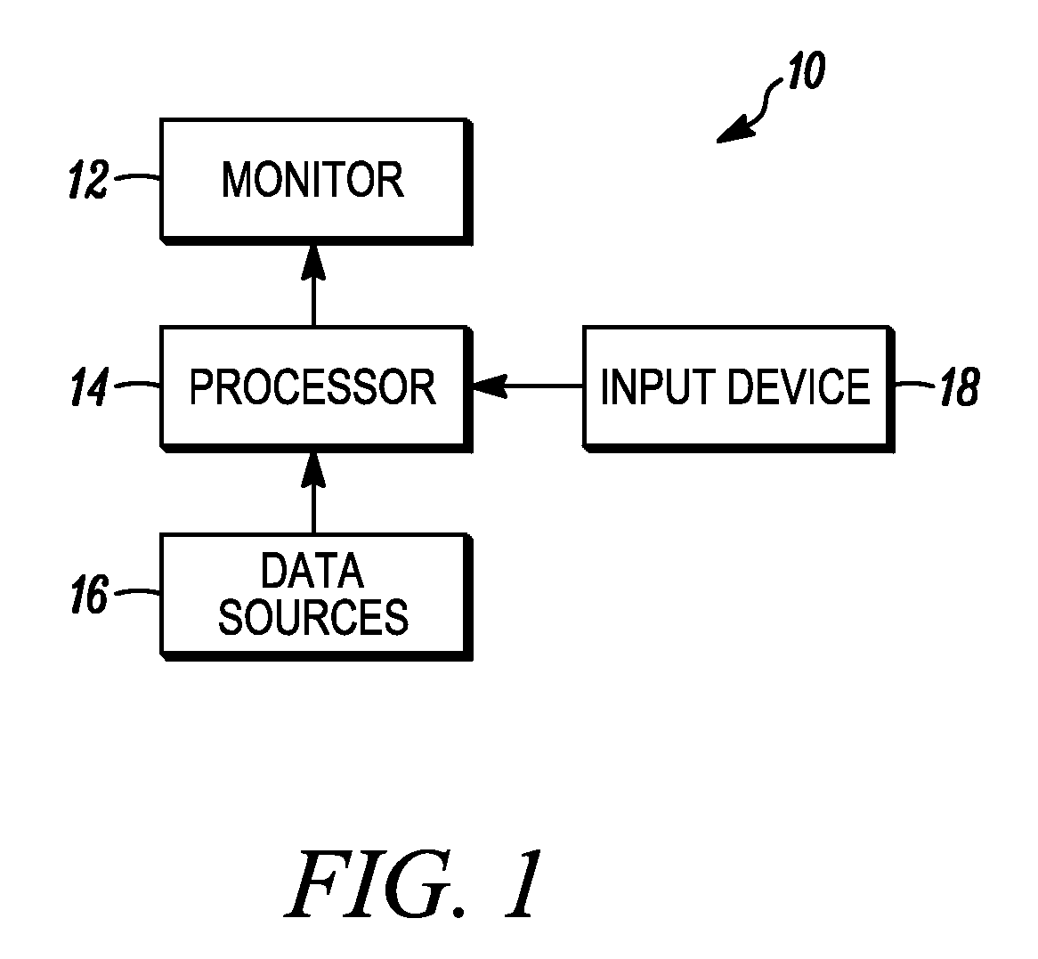
[0014]FIG. 1 is a functional block diagram of a generalized avionics display system 10. Display system 10 is required navigational performance (RNP) capable. That is, display system is capable of monitoring aircraft position with the degree of accuracy required under RNP protocols established by the Federal Aviation Administration. Display system 10 includes at least one monitor 12, a processor 14, and a plurality of data sources 16. In certain embodiments, display system 10 may also include a user input 18, such as a keyboard and / or a cursor control device (e.g., a trackball). Processor 14 includes at least first and second inputs, which ar...


PUM


Abstract

A method is provided for indicating the boundaries of a required navigational performance (RNP) corridor on an aircraft's map display. The method includes the steps of producing an aircraft leg segment symbol on the map display, establishing an RNP value, and scaling the RNP value to the map display field of view. The method further includes the step of generating an RNP corridor boundary graphic on the map display offset from the aircraft leg segment symbol by the scaled RNP value.

Description

FIELD OF THE INVENTION[0001]The present invention relates generally to vehicular display systems, and, more particularly, to an aircraft display system and method for indicating the boundaries of a required navigational performance corridor on an aircraft's navigational map display.BACKGROUND OF THE INVENTION[0002]The Federal Aviation Administration has developed required navigation performance (RNP) protocols to facilitate the management of air traffic. Under these protocols, RNP values (e.g., 0.1 to 30 nautical miles) may be assigned to various particular segments, or legs, of an aircraft's flight plan. For example, when an aircraft approaches an airfield, the aircraft may be assigned a particular flight plan segment, or landing leg, by the air traffic controller. Depending upon air traffic, the air traffic controller may also communicate to the aircraft's crew (e.g., pilot) an RNP value associated with the landing leg (e.g., 2.0 nautical miles). The RNP value defines an airspace ...

Claims


Application Information

Patent Timeline
Patent Type & Authority Applications(United States)
IPC IPC(8): G01C21/00
CPCG01C23/005G08G5/0021G08G5/0052G08G5/025
Inventor AUNG, YAN L.
Owner HONEYWELL INT INC
Why Eureka
Try Eureka