
Image forming apparatus and method to improve image quality thereof

a technology of image forming apparatus and image quality, which is applied in the field of improving image quality, can solve the problems of increasing the amount of data to be processed, rough halftone images, and limiting the number of neighboring grays, so as to improve image quality and improve printing quality

Inactive Publication Date: 2008-12-18
S PRINTING SOLUTION CO LTD
View PDF11 Cites 7 Cited by
  • Summary
  • Abstract
  • Description
  • Claims
  • Application Information

AI Technical Summary

Benefits of technology

[0011]The present general inventive concept provides an image forming apparatus to improve printing quality in which a plurality of gray levels are generated using weighted values according to locations of reference pixels, and a method to improve image quality thereof.
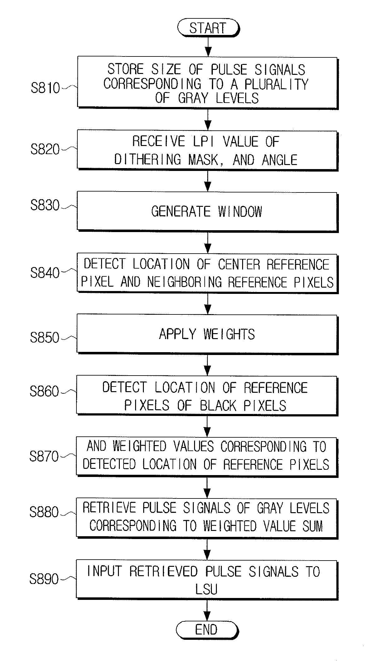
[0022]The foregoing and / or other aspects and utilities of the present general inventive concept may also be achieved by providing a method to improve image quality, the method including receiving a lines per inch (LPI) value of a dithering mask and an angle, generating a window of a predetermined size based on the LPI value and the angle, detecting locations of a center reference pixel and neighboring reference pixels in the window, applying weighted values to the reference pixels corresponding to the detected locations of the center reference pixel and the neighboring reference pixels and determining a dot size of the center reference pixel based on weighted values corresponding to locations of black pixels of the center reference pixel and the neighboring reference pixels.

Problems solved by technology

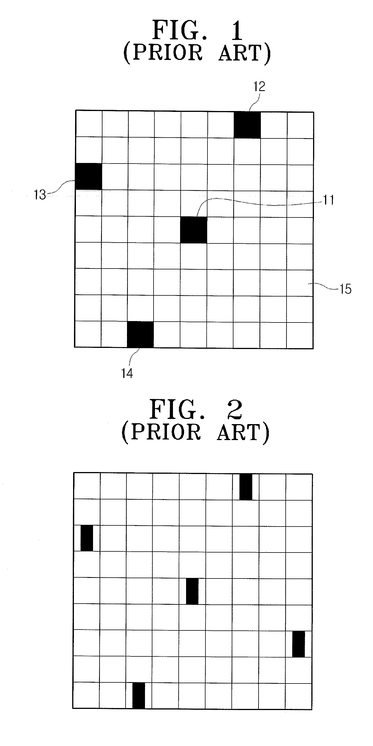
However, halftone images look rough, especially, in lighter areas, because halftone processing simply turns on or off pixels or dots.
Therefore, an amount of data to be processed is increased, and a number of grays is limited by the number of neighboring pixels.

Method used


Image

  • Image forming apparatus and method to improve image quality thereof
  • Image forming apparatus and method to improve image quality thereof
  • Image forming apparatus and method to improve image quality thereof

Examples


Embodiment Construction

[0044]Reference will now be made in detail to embodiments of the present general inventive concept, examples of which are illustrated in the accompanying drawings, wherein like reference numerals refer to the like elements throughout. The embodiments are described below in order to explain the present general inventive concept by referring to the figures.

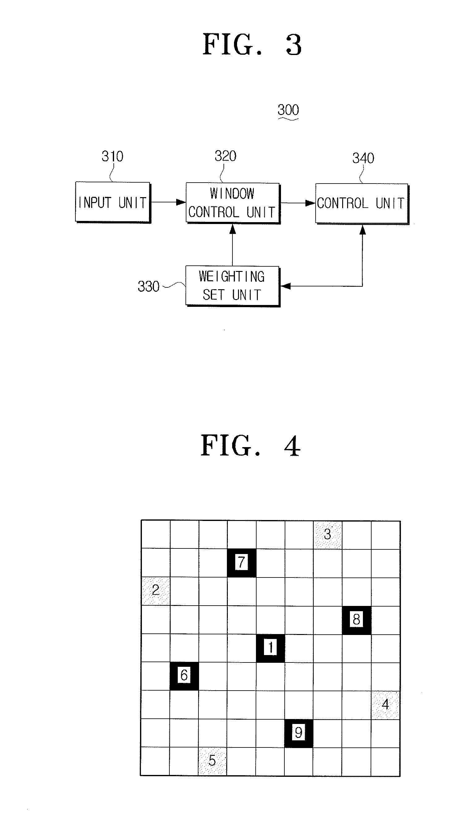
[0045]FIG. 3 is a block diagram illustrating an image forming apparatus 300 according to an exemplary embodiment of the present general inventive concept. Referring to FIG. 3, an image forming apparatus may include an input unit 310, a window control unit 320, a weighting set unit 330, and a control unit 340.

[0046]The input unit 310 receives a binary image, a lines per inch (LPI) value of a dithering mask and an angle.

[0047]The LPI value, a number of input lines per inch value, represents a screen frequency. The LPI value may be computed by Equation 1.

LPI value=resolution / Euclidean distance between reference pixels  [Equation 1]

[004...


PUM


Abstract

An image forming apparatus to improve image quality. The image forming apparatus includes a window control unit to generate a window of a predetermined size using a lines per inch (LPI) value of a dithering mask and an angle, and to detect locations of a center reference pixel and neighboring reference pixels in the window, a weighting set unit to apply weighted values to the reference pixels based on locations of the detected center reference pixel and the neighboring reference pixels, and a control unit to determine a dot size of the center reference pixel corresponding to weighted values corresponding to locations of black pixels of the center reference pixel and neighboring reference pixels. Accordingly, image quality is improved by generating dots corresponding to a plurality of gray levels based on weighted values.

Description

CROSS-REFERENCE TO RELATED APPLICATIONS[0001]This application claims priority under 35 U.S.C. § 119 (a) from Korean Patent Application No. 10-2007-0058418, filed on Jun. 14, 2007, in the Korean Intellectual Property Office, the disclosure of which is incorporated herein in its entirety by reference in its entirety.BACKGROUND OF THE INVENTION[0002]1. Field of the Invention[0003]The present general inventive concept relates to a method to improve image quality and an apparatus that uses the image quality improving method, and more particularly, to an image forming apparatus to enhance quality of an image using weighted values according to locations of reference pixels and a method to improve the image quality.[0004]2. Description of the Related Art[0005]Generally, a monochromic or color laser printer prints images on a subpixel-based gray scale. A gray scale representation in which each pixel is expressed in various gray levels requires a large amount of data to be processed. Accordin...

Claims


Application Information

Patent Timeline
IPC IPC(8): B41J2/21H04N1/46
CPCH04N1/4056H04N1/4058H04N1/40037H04N1/4057H04N1/60
Inventor LEE, HO-KEUNSHIN, SANG-YOUN
Owner S PRINTING SOLUTION CO LTD
Learn More