System and method for adjusting sensitivity of an acoustic sensor

Active Publication Date: 2008-12-18
ADEMCO INC
View PDF6 Cites 14 Cited by
  • Summary
  • Abstract
  • Description
  • Claims
  • Application Information

AI Technical Summary

Benefits of technology

[0006]Disclosed is a method for remotely adjusting the sensitivity level of an acoustic detector using a remote control device by

Problems solved by technology

This adjustment process is time consuming and cumbersome.
Because the process is cumbersome, install

Method used


Image

  • System and method for adjusting sensitivity of an acoustic sensor
  • System and method for adjusting sensitivity of an acoustic sensor
  • System and method for adjusting sensitivity of an acoustic sensor

Examples


Embodiment Construction

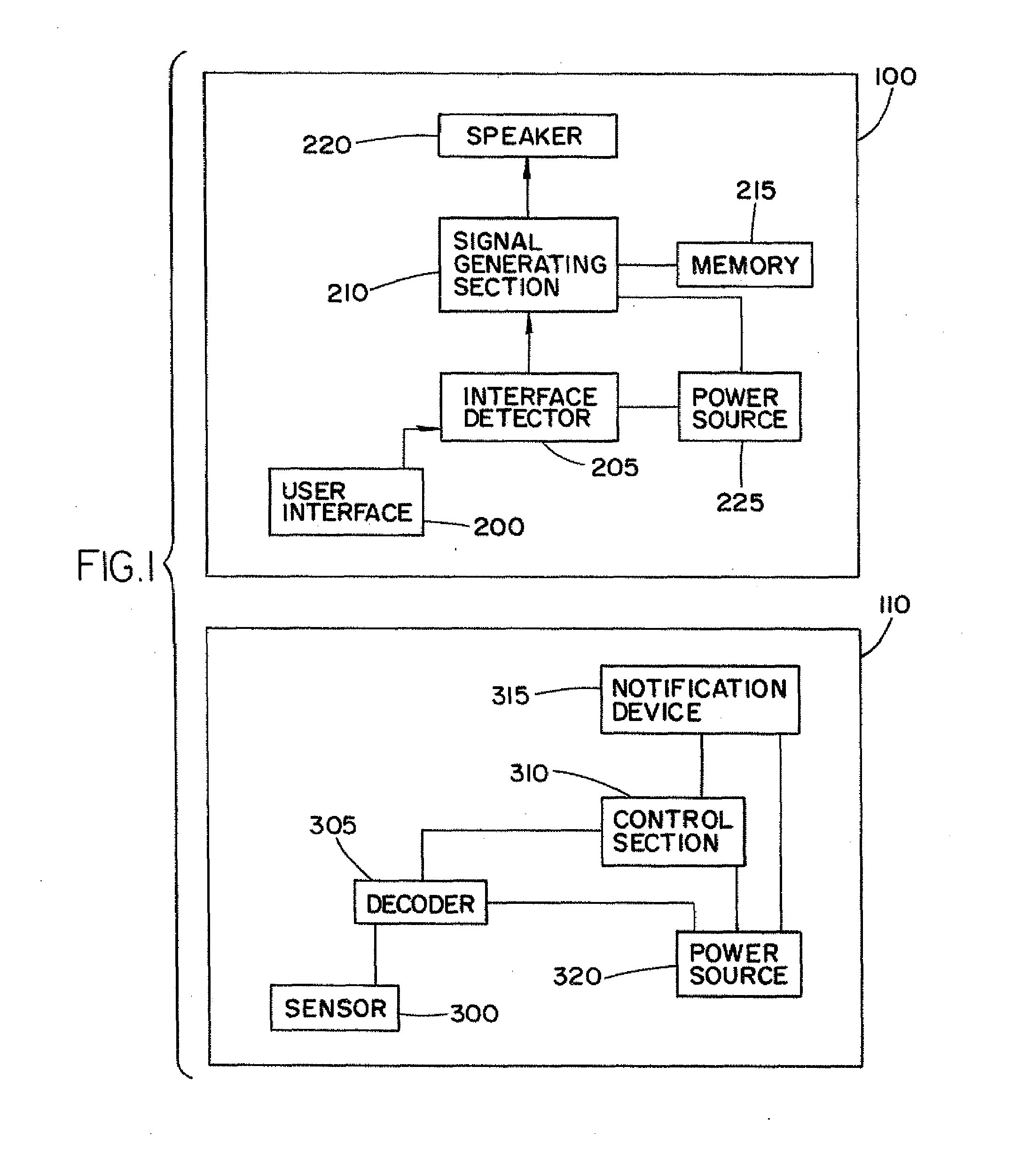
[0023]FIG. 1 illustrates the remote control system in which a remote control device 100 is used to adjust the sensitivity of an acoustic detector 110. The remote control device 100 can be any device capable of transmitting a calibrated acoustic signal. In one embodiment, the remote control device 100 is a glass break simulator. For example, the remote control device 100 can be the glass break simulator as described in U.S. Pat. No. 5,341,122 issued to Stephen Rickman, which is hereby incorporated by reference.

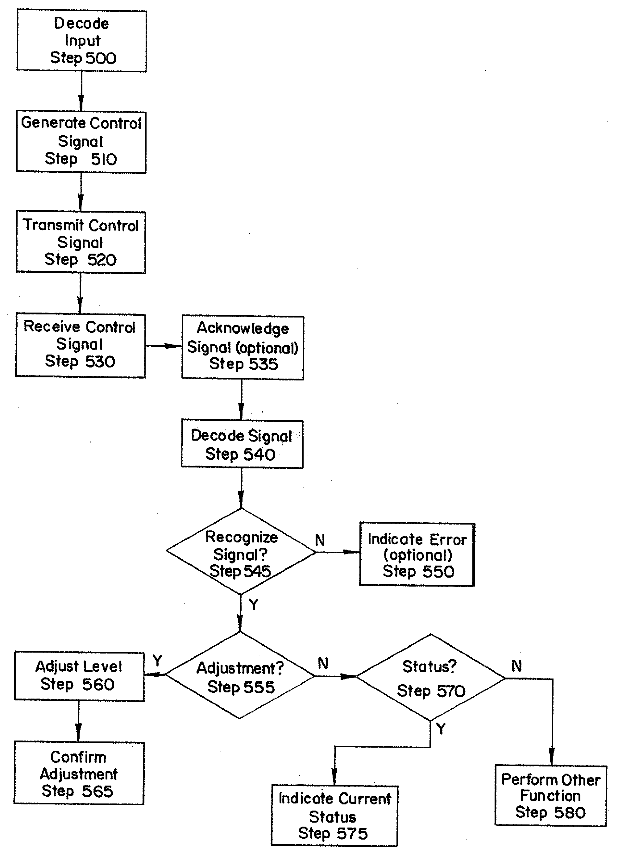
[0024]The remote control device 100 may be configured to generate a control signal to control specific features of an acoustic detection.

[0025]The remote control device 100 includes a user interface section 200 adapted to allow a user to input a control instruction. The user interface section 200 can be a DIP switch, a jog dial, or an arrow key or button. Alternatively, the user interface section 200 can be an alphanumeric keypad. The remote control device 100 also includes an ...


PUM


Abstract

A method of adjusting a sensitivity of an acoustic detector. The acoustic detector receives a signal from a remote device. The signal embodies an operating instruction for the acoustic detector. The signal is decoded into an operating instruction for the acoustic detector. The sensitivity of the acoustic detector is adjusted according to the operating instruction. The acoustic detector can increase or decrease the sensitivity. After the sensitivity is adjusted, the acoustic detector sends a confirmation of the adjustment to the user.

Description

FIELD OF THE INVENTION[0001]The invention relates to security systems, communication systems and acoustic detectors. More particularly, the invention relates to a method and system for remotely adjusting the sensitivity of an acoustic sensor using a remote control device.BACKGROUND[0002]Acoustic detectors are commonly used to detect and indicate attempts to break into premises. The most common acoustic detector is a glass breakage detector. The detector generates an alarm signal when the sound of a breaking window is detected. Typically, the detectors are remotely mounted from the protected glass and are attached to a ceiling or a wall. The location of the detector is dependent on the size of the protected area and a number of other mounting restrictions that are manufacturer specific.[0003]The detectors rely on detecting the sound of breaking glass by sensing one or more known frequency components associated with the sound of breaking glass. When the glass break detector is install...

Claims


Application Information

Patent Timeline
IPC IPC(8): H04B17/00G08B21/00
CPCG08B13/04G08B13/1672G08B29/22
Inventor PIEL, KEVIN G.MARTIN, CHRISTOPHER D.SMITH, RICHARD A.PETEK, TOM R.
Owner ADEMCO INC
Why Eureka
Try Eureka