Systems and methods for an environmental control system including a motorized vent covering

a technology of environmental control system and motorized vent, which is applied in the direction of instruments, heating types, static/dynamic balance measurement, etc., can solve the problems of inefficient and costly heating or cooling the upstairs, waste of energy, and time-consuming

Inactive Publication Date: 2011-11-03
ENERGY EYE
View PDF32 Cites 50 Cited by
  • Summary
  • Abstract
  • Description
  • Claims
  • Application Information

AI Technical Summary

Benefits of technology

[0009]Systems and methods for an environment control system that includes a motorized vent coverin

Problems solved by technology

Rising energy costs have driven manufacturers to make an effort to make these systems more energy efficient; however, even the most energy efficient HVAC systems can still waste energy by heating or cooling unoccupied spaces within a building.
Accordingly, it can be in

Method used


Image

  • Systems and methods for an environmental control system including a motorized vent covering
  • Systems and methods for an environmental control system including a motorized vent covering
  • Systems and methods for an environmental control system including a motorized vent covering

Examples


Embodiment Construction

.”

BRIEF DESCRIPTION OF THE DRAWINGS

[0012]Features, aspects, and embodiments are described in conjunction with the attached drawings, in which:

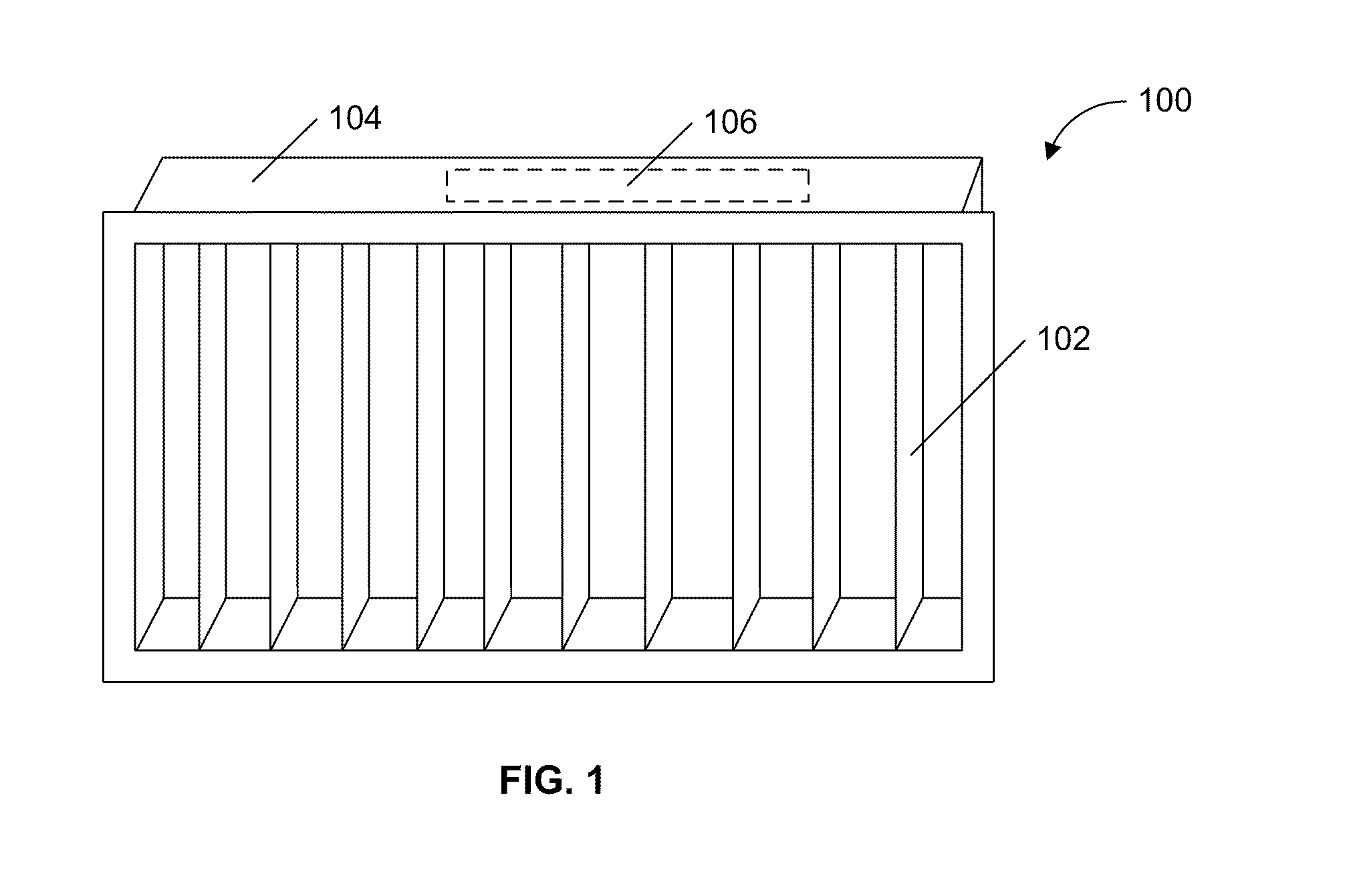
[0013]FIG. 1 is a diagram illustrating an example motorized vent covering in accordance with one embodiment;

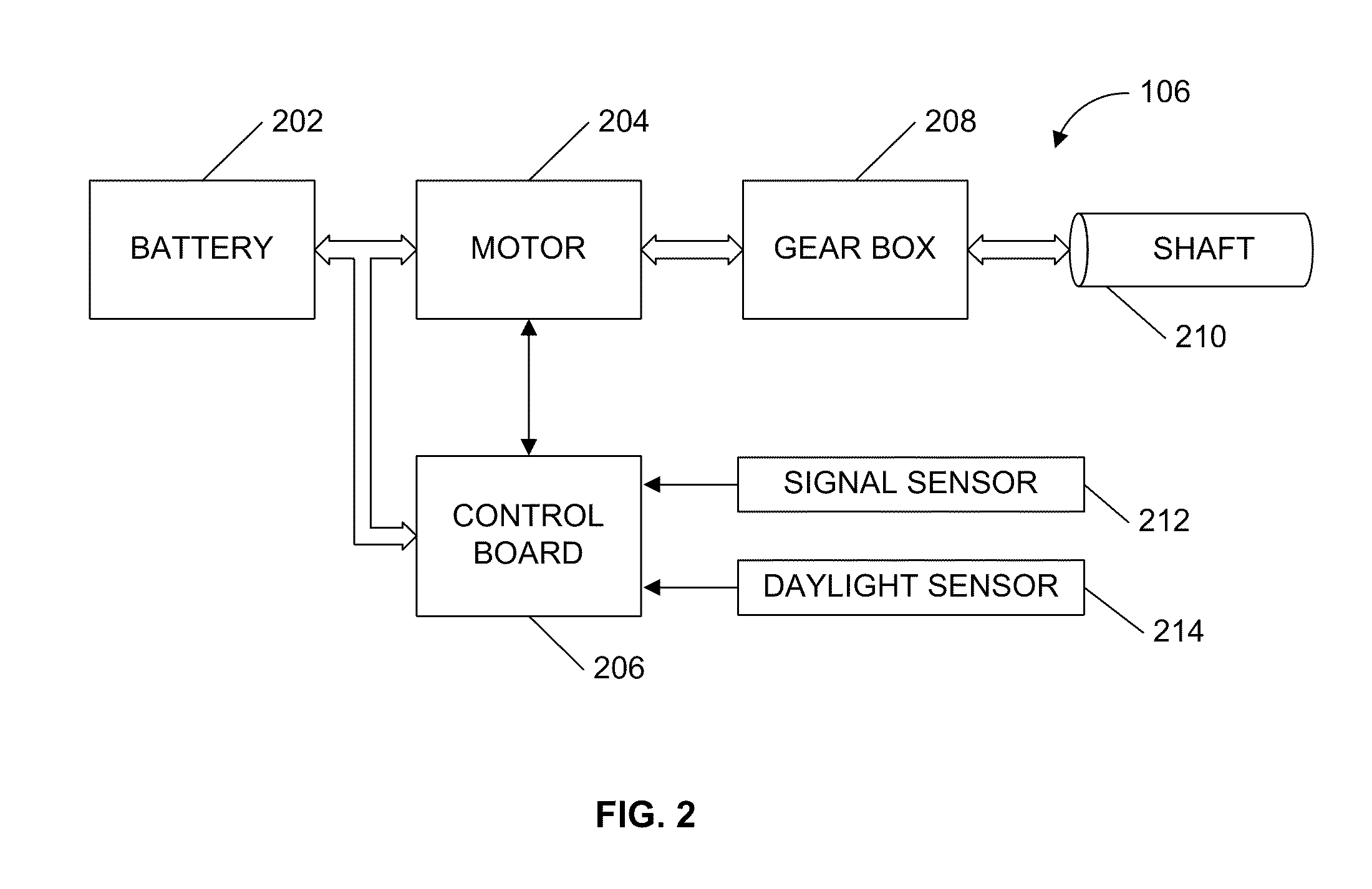
[0014]FIG. 2 is a diagram illustrating an example actuator for use in the motorized vent covering of FIG. 1;

[0015]FIG. 3 is a flow chart illustrating an example process for upgrading a room to include the motorized vent covering of FIG. 1; and

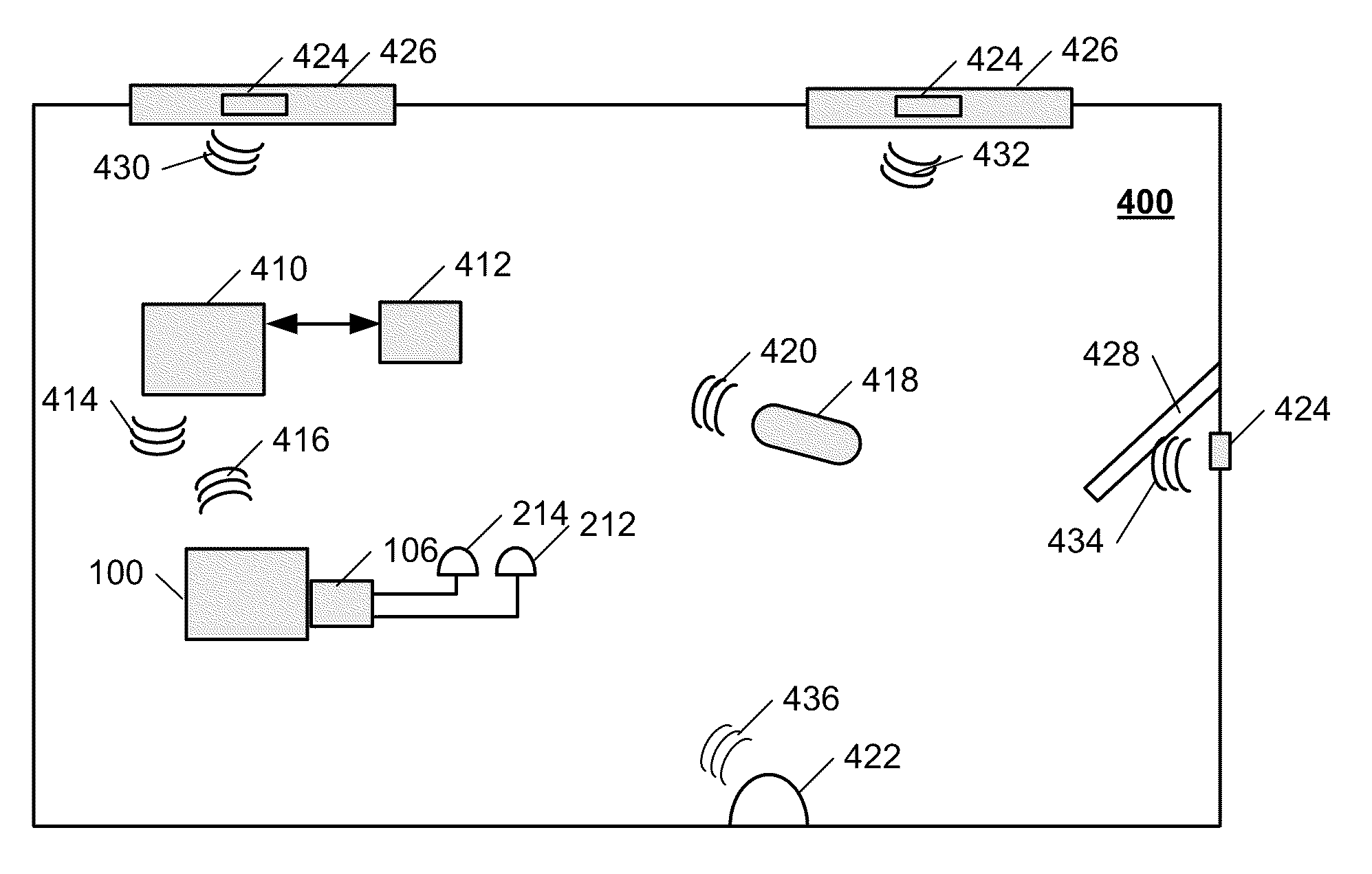
[0016]FIG. 4 is a diagram illustrating an example environment control system that can include the motorized vent covering of FIG. 1 in accordance with one embodiment.

DETAILED DESCRIPTION

[0017]The following detailed description is directed to certain specific embodiments. However, it will be understood that these embodiments are by way of example only and should not be seen as limiting the systems and methods described herein to the specific embodiments, architectures, etc. In this description, refer...


PUM


Abstract

A motorized vent covering for an air vent of the environment control system, the motorized vent covering comprising an air flow restrictor for controlling air flow through the vent; and an actuator, the actuator including a motor configured to drive the air flow restrictor to control the flow of air from the vent, and a controller in communication with the motor, the controller configured to provide operating instructions to the motor to open or close the air flow restrictor to adjust the flow of air through the air vent.

Description

RELATED APPLICATIONS[0001]This application claims priority as a continuation-in-part under 35 U.S.C. §120 to copending U.S. patent application Ser. No. 12 / 772,900 entitled “SYSTEMS AND METHODS FOR A MOTORIZED VENT COVERING IN AN ENVIRONMENT CONTROL SYSTEM,” filed on May 3, 2010, which is incorporated herein by reference in its entirety.BACKGROUND[0002]1. Technical Field[0003]The embodiments described herein are related to automated environment control system operation and more particularly, to systems and methods for controlling the operation of a motorized vents in an environment control system.[0004]2. Related Art[0005]Heating, ventilating, and air conditioning (HVAC) systems provide control over the indoor environment of buildings through heating, cooling, and air circulation. Rising energy costs have driven manufacturers to make an effort to make these systems more energy efficient; however, even the most energy efficient HVAC systems can still waste energy by heating or cooling...

Claims


Application Information

Patent Timeline
IPC IPC(8): G05D23/19G05D7/06
CPCF24F11/0001F24F11/0012F24F13/1426F24F2013/1433F24F2011/0049F24F2011/0068F24F13/15F24F11/30F24F2110/10F24F2130/20F24F11/56F24F2120/00F24F11/46F24F11/79
Inventor SCHARF, RICHARDHEALD, ROGER
Owner ENERGY EYE
Why Eureka
Try Eureka