
Method and apparatus for transmitting and receiving channel quality indicator in communication system

a communication system and channel quality indicator technology, applied in the field of communication systems, can solve problems such as increasing resource was

Active Publication Date: 2008-12-18
SAMSUNG ELECTRONICS CO LTD
View PDF6 Cites 65 Cited by
  • Summary
  • Abstract
  • Description
  • Claims
  • Application Information

AI Technical Summary

Benefits of technology

[0024]According to a further aspect of the present invention, a base station apparatus is provided for receiving a Channel Quality Indicator (CQI) in a communication system. The base station apparatus includes a demultiplexer for demultiplexing multiplexed data received from a terminal to extract a CQI, and a data reception controller for controlling reception of the data according to scheduling information generated by a scheduler. The base station apparatus also includes a packet data demodulator for demodulating packet data received from the demultiplexer und...

Problems solved by technology

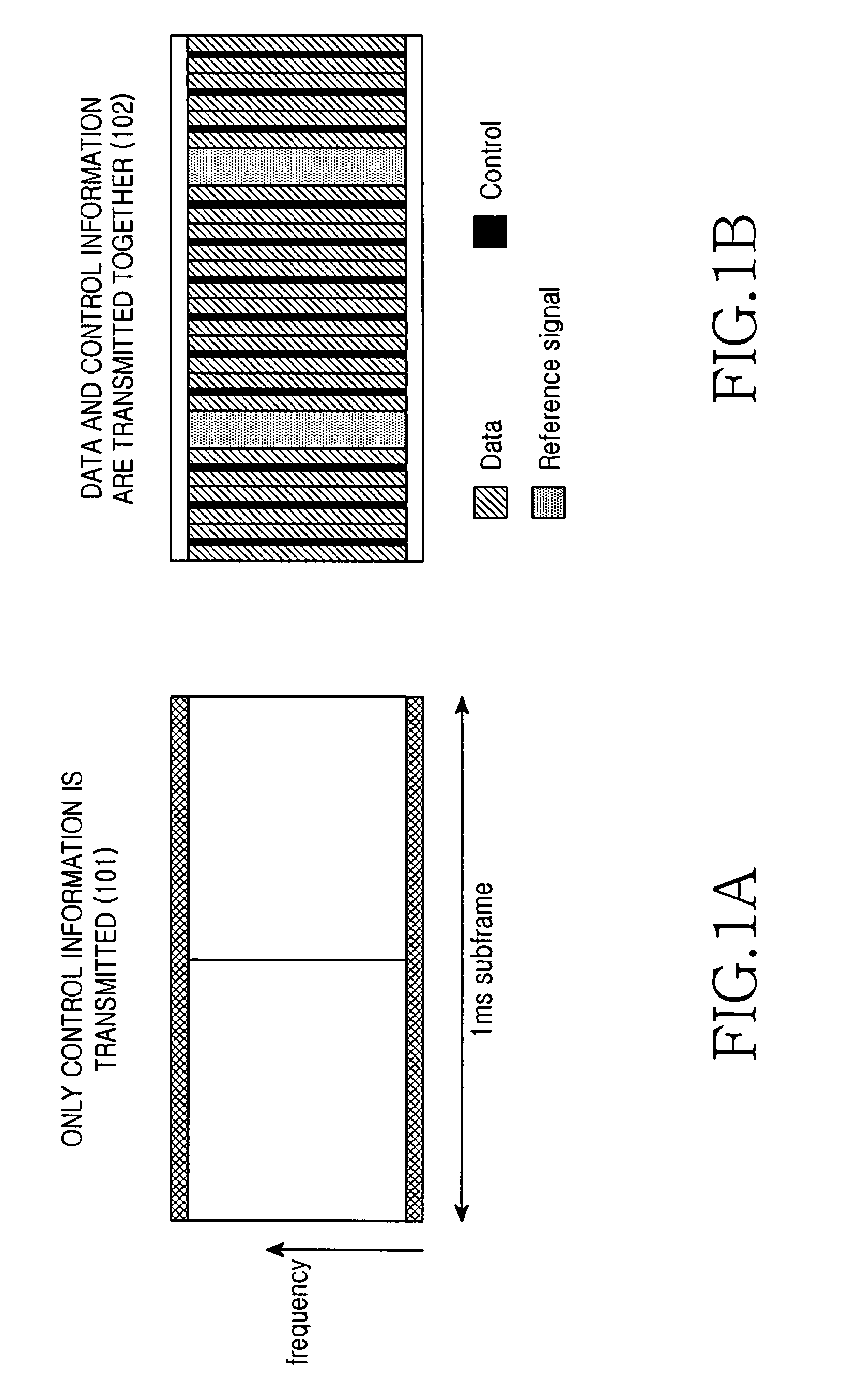
This is because the simultaneous transmission of packet data and control information in the same transmission interval may increase a Peak to Average Power Ratio (PAPR) as it may not satisfy the single carrier characteristic.
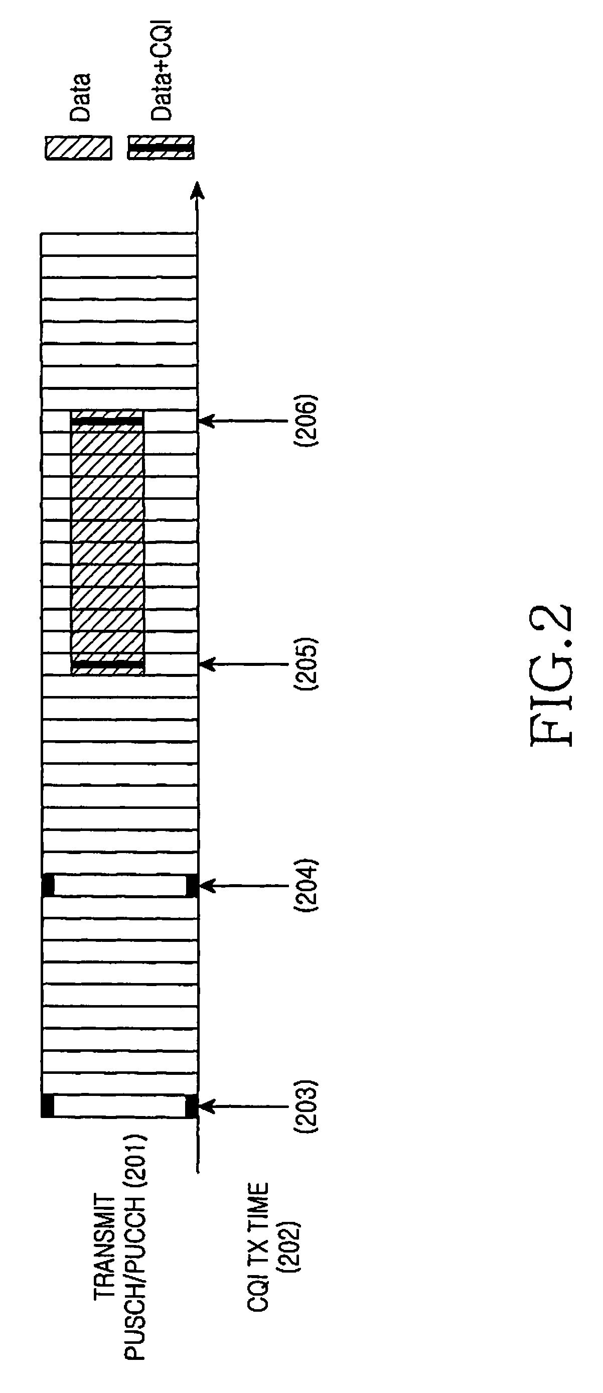
However, in the case where the amount of CQI information is large, even though resources are allocated, the terminal may not use the allocated resources at the CQI transmission times 205 and 206, increasing the resource waste.
However, for this, the base station should send a new resource allocation message for scheduling, and sending signaling only for this purpose may cause signaling overhead.

Method used


Image

  • Method and apparatus for transmitting and receiving channel quality indicator in communication system
  • Method and apparatus for transmitting and receiving channel quality indicator in communication system
  • Method and apparatus for transmitting and receiving channel quality indicator in communication system

Examples


first embodiment

[0046]FIG. 3A illustrates a CQI transmission scheme according to the present invention. In FIG. 3A, the horizontal axis represents the time domain, and the vertical axis presents the frequency domain of transmission over PUSCH / PUCCH 301. One rectangle represents one Transmission Time Interval (TTI) as a basic transmission unit, referred to as one sub-frame 310 of radio frame 309. In LTE, one TTI is assumed as 1 ms, and it occupies a size of allocated frequency resources along the frequency domain. FIG. 3A shows only uplink transmission of one terminal. The hatched parts represent the frequency region (or frequency band) allocated to the terminal in the entire frequency region, and the remaining frequency regions will be allocated to other terminals. The region composed of only the hatched parts represents transmission of only packet data, while the region mixed of hatched parts and black strips represents multiplexing of data transmission and CQI transmission. It is assumed in FIG. ...

second embodiment

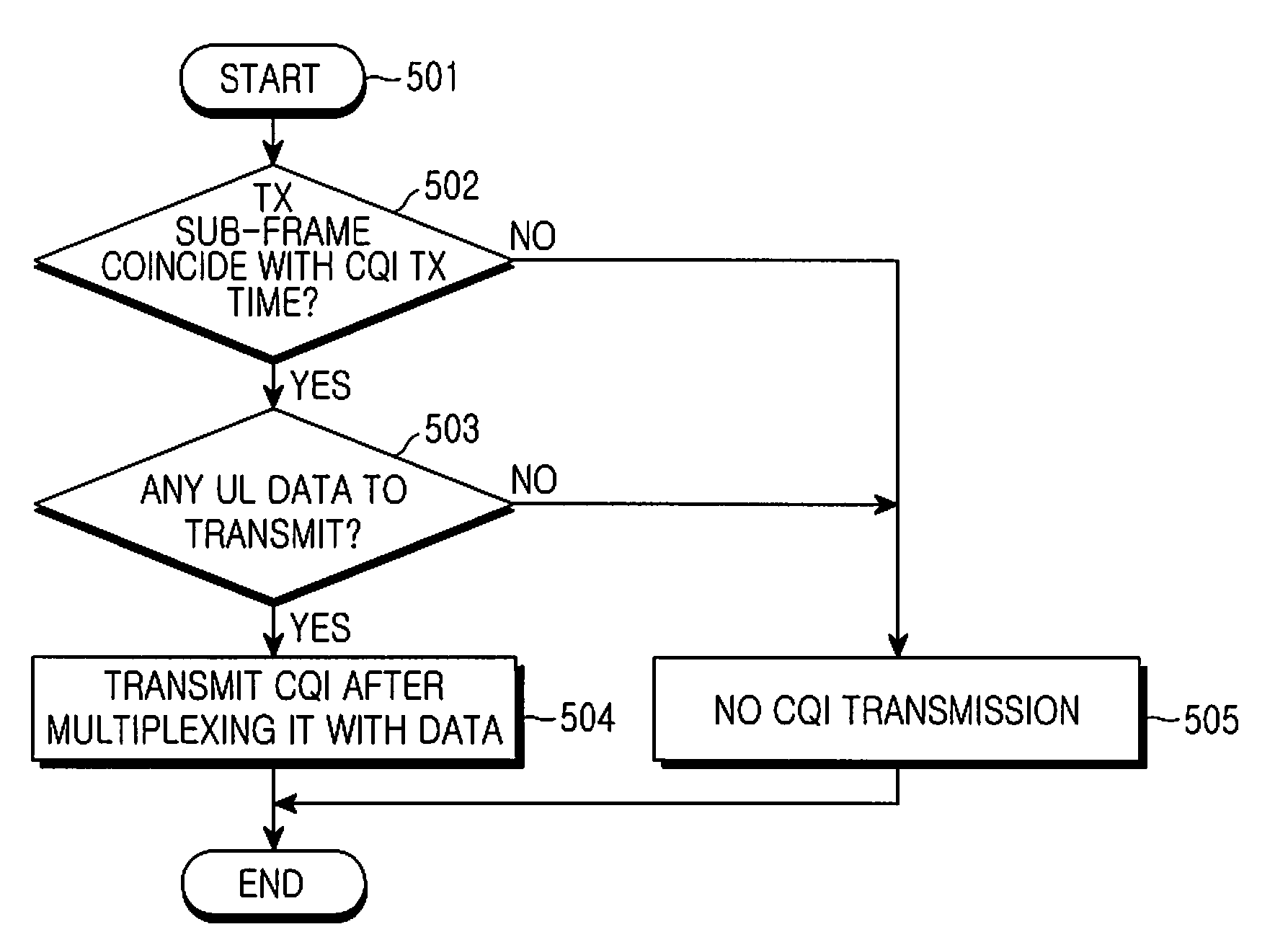
[0065]In the present invention, a CQI transmission period of a terminal is previously set, and only when the there is an uplink scheduling grant transmitted to the terminal every CQI transmission period or only when the terminal performs initial transmission on uplink data, the terminal punctures a part of data to insert CQI information therein, and multiplexes the CQI information and uplink data before transmission.

[0066]The second embodiment of the present invention is the same as the first embodiment of the present invention in the method of, when there is data to transmit over the uplink, puncturing a part of data to insert CQI information therein and multiplexing the CQI information and uplink data before transmission. However, the second embodiment of the present invention is different from the first embodiment in that it multiplexes the CQI information and uplink data only when it receives a scheduling grant. That is, the second embodiment of the present invention permits tra...

third embodiment

[0080]the present invention determines whether to make CQI transmission based on occurrence of uplink data, reception of an uplink scheduling grant, initial transmission indication of data, and / or previous CQI transmission record. That is, the terminal multiplexes CQI and packet data before transmission only (i) when uplink data has occurred, (ii) when it has received an uplink scheduling grant, and / or (iii) when no CQI transmission has been made for a particular interval while data undergoes its initial transmission.

[0081]FIG. 14 illustrates CQI transmission 1401 according to the third embodiment of the present invention. Like the first embodiment of the present invention, the third embodiment of the present invention shown FIG. 14 transmits CQI when uplink data transmission occurs at a CQI transmission time 1402.

[0082]As illustrated in FIG. 14, a terminal always transmits CQI together with packet data during initial transmission of uplink data as shown by 1403. Next, the terminal ...


PUM


Abstract

A method and apparatus for transmitting / receiving a Channel Quality Indicator (CQI) in a communication system are provided. It is determined whether there is any uplink data to transmit, when a CQI transmission time arrives according to a predetermined CQI transmission period. If there is uplink data to transmit, a part of the uplink data is punctured to insert the CQI therein, and the inserted CQI is multiplexed with the uplink data before transmission. It is determined whether there is any uplink data to receive from a terminal, when a CQI reception time arrives according to a predetermined CQI transmission period. If there is uplink data to receive, the uplink data is received from the terminal, and the received uplink data is demultiplexed to extract the CQI.

Description

PRIORITY[0001]This application claims priority under 35 U.S.C. §119(a) to a Korean Patent Application filed in the Korean Intellectual Property Office on Jun. 13, 2007 and assigned Serial No. 2007-57849, and a Korean Patent Application filed in the Korean Intellectual Property Office on Jun. 20, 2007 and assigned Serial No. 2007-60789, the disclosures of both of which are incorporated herein by reference.BACKGROUND OF THE INVENTION[0002]1. Field of the Invention[0003]The present invention relates generally to a communication system, and more particularly, to a method and apparatus for transmitting and receiving uplink control information.[0004]2. Description of the Related Art[0005]Intensive research is being conducted in the field of mobile communication systems on Orthogonal Frequency Division Multiplexing (OFDM), which is a scheme useful for high-speed data transmission in radio channels, and / or on Single Carrier—Frequency Division Multiple Access (SC-FDMA), which is a scheme sim...

Claims


Application Information

Patent Timeline
IPC IPC(8): H04Q7/00H04J3/00
CPCH04L1/0013H04L1/0026H04L1/0027H04L1/003H04L1/0068H04L1/1812
Inventor HEO, YOUN-HYOUNGLEE, JU-HOCHO, JOON-YOUNG
Owner SAMSUNG ELECTRONICS CO LTD
Learn More