Torque Overcorrection Model

a technology of overcorrection and model, applied in the field of computer-aided orthodontia, can solve the problems of difficult to create a pure translational movement of a tooth, difficult to control, and inconvenient to implemen

Inactive Publication Date: 2008-12-18
ORMCO CORP
View PDF6 Cites 12 Cited by
  • Summary
  • Abstract
  • Description
  • Claims
  • Application Information

AI Technical Summary

Benefits of technology

[0014]In preferred embodiments, the torque interaction is computed to compensate for tooth tilt resulting from misalignment of the force vector applied by the archwire with the tooth center of resistance. Furthermore, the torque interaction is computed at

Problems solved by technology

In orthodontics it is difficult to create a pure translational movement of a tooth, or to control rotation of the tooth in what is called the Y-Z plane.
This problem is most acute wh

Method used


Image

  • Torque Overcorrection Model
  • Torque Overcorrection Model
  • Torque Overcorrection Model

Examples


Embodiment Construction

[0034]In accordance with the present invention, a computer aided orthodontia design system utilizes tooth shape data to approximate the actual translational and angular effects. This process is performed after appliance design and prior to final fabrication.

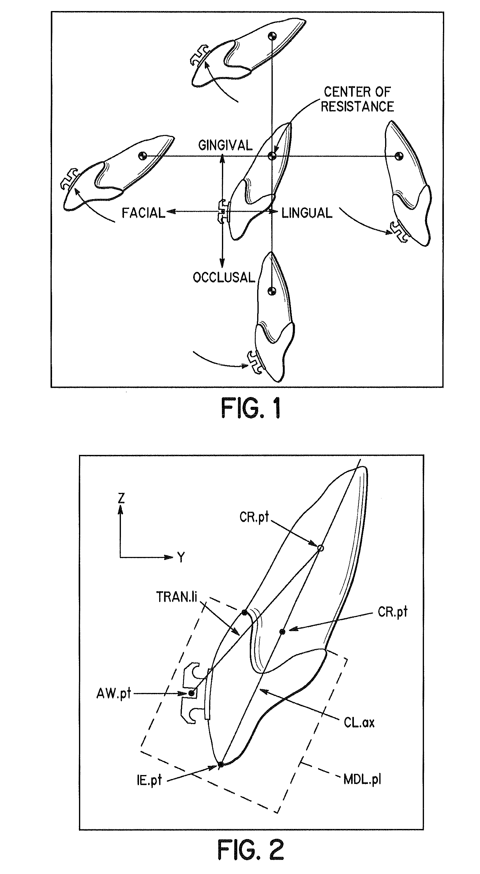
[0035]Referring now to FIG. 2, the tooth landmarks used in accordance with principles of the present invention may be identified:

[0036]MDL.pl (Mid Developmental Lobe Plane)

[0037]CC.pt (Cervical Center Point)

[0038]CL.ax (Crown Long Axis)

[0039]FEGJ.pt (facial Enamel Gingival Junction Point)

[0040]IE.pt (Incisal Edge Point): Found by projecting a line normal to MDL.pl through BC.pt

[0041]Crown Height (CH.li): The distance from IE.pt to FEGJ.pt. This is used to find CR.pt by using data from a lookup table proportionate to CH.li along CL.ax from CC.pt extending toward the root tip.

[0042]CR.pt (Center of Resistance Point): Found by extending CL.ax gingivally by an amount proportional to the length of the line segment CH.li (approximate c...


PUM

PropertyMeasurementUnit
Forceaaaaaaaaaa
Angleaaaaaaaaaa
Torqueaaaaaaaaaa

Abstract

A custom orthodontic appliance comprised of brackets to be positioned on a patient's teeth, and an archwire, is customized to provide a desired torque to a tooth by selecting an angle for the slot of at least one bracket so as to provide a torque interaction between that bracket slot and the archwire. The torque interaction is computed to compensate for tooth tilt resulting from misalignment of the force vector applied by the archwire with the tooth center of resistance. The torque interaction is computed at the desired final position of the teeth, and may be computed to provide for an applied torque even where the tooth is positioned in the desired final tooth position to compensate for force diminution. Material properties of the archwire and the relative archwire slot geometry are evaluated to determine an archwire/slot angular offset in which torque is applied to the bracket.

Description

CROSS REFERENCE TO RELATED APPLICATIONS[0001]This application claims benefit of U.S. Provisional Application 60 / 916,189, filed on May 4, 2007, which is incorporated herein by reference.[0002]This application is related to:[0003]U.S. Pat. No. 5,431,562 issued Jul. 11, 1995 and Published International Patent Application No. PCT / US00 / 35558, each of which is incorporated in their entirety herein.[0004]International Patent Application No. WO2004 / 028391, which is assigned to the assignee hereof and hereby incorporated by reference in its entirety.[0005]U.S. patent application Ser. No. 10 / 528,036, filed Mar. 16, 2005, which is a U.S. National Stage application of International Application No. PCT / US2003 / 030917, filed on Sep. 26, 2003, which claims the benefit of U.S. Provisional Patent Application Ser. No. 60 / 413,712, filed Sep. 26, 2002, both hereby expressly incorporated by reference herein.[0006]U.S. patent application Ser. No. 09 / 941,591, which is a continuation of International Patent...

Claims


Application Information

Patent Timeline
IPC IPC(8): A61C7/00
CPCA61C7/002Y10T29/49568A61C7/146A61C7/12
Inventor ANDREIKO, CRAIG A.
Owner ORMCO CORP
Why Eureka
Try Eureka