Turbojet Engine Mounting Structure For Aircraft

a technology for aircraft and turbojet engines, which is applied in the direction of power plant construction, power plant type, aircraft power plant, etc., can solve the problems of heightened disturbance, large drag and loss of turbojet engine yield and fuel consumption, etc., and achieves convenient and quick operation, safe and satisfactory transfer, and the effect of reducing the rigid structure of the engine moun

Active Publication Date: 2008-12-25
AIRBUS OPERATIONS (SAS)
View PDF2 Cites 16 Cited by
  • Summary
  • Abstract
  • Description
  • Claims
  • Application Information

AI Technical Summary

Benefits of technology

[0019]Therefore in the preferred, but non-limiting case, in which the above-indicated frame is the aft closure frame of the box, the proposed engine mount advantageously provides original, high-performance securing of these aft closure frames onto the longitudinal central box of the rigid structure, through the presence of the side extensions which are therefore fully secured to one of the transverse ribs forming the longitudinal central box. The presence of this part made in a single piece, that is a constituent part of the central box and sets up a mechanical junction between this box and each of the two aft closure frames, effectively allows safe, satisfactory transfer to be obtained of those loads transiting in the side boxes in the direction of the central box.
[0020]Also, with this solution, the mechanical joining of the aft closure frames onto the central box is very easy and quick to perform, since the positioning of the side extensions used to join these closure frames is obtained automatically when positioning the transverse rib of the central box carrying these extensions. The assembly operations of the rigid structure of the engine mount can therefore be advantageously shortened.
[0025]Also, for each of the two side extensions, an outer surface of the extension support is positioned substantially in a same plane as an outer surface of the associated side panel. In this way good aerodynamic continuity is obtained on the side outer surfaces of the central box, despite the presence of extensions projecting outwardly from the box.
[0033]In this manner, these specificities respectively enable the longitudinal central box to remain sealed by housing the supports for the additional extensions in the throughways for additional extensions provided on the side panels, and provide good aerodynamic continuity on the side outer surfaces of the central box, despite the presence of the additional extensions projecting outwardly from the box.
[0038]This advantageously allows gains to be achieved in terms of drag, turbojet engine yield and fuel consumption.

Problems solved by technology

Therefore, in this precise case in which the engine mount, in the form of a large-sized box, is arranged in the vicinity of the central case of the turbojet engine, this engine mount inevitably causes major disturbances of the secondary airstream leaving the annular fan duct, which directly translates as major drag and losses in terms of turbojet engine yield and fuel consumption.
In addition, these disturbances are heightened by the presence of the thrust mount device of side link type, located at the outlet of the annular fan duct.
However this type of rigid structure, also called primary structure of the engine mount, has a non-negligible drawback lying in the lack of satisfactory means to ensure high-performance securing of all the frames of each side box onto the longitudinal central box, whilst offering easy mounting.

Method used


Image

  • Turbojet Engine Mounting Structure For Aircraft
  • Turbojet Engine Mounting Structure For Aircraft
  • Turbojet Engine Mounting Structure For Aircraft

Examples


Embodiment Construction

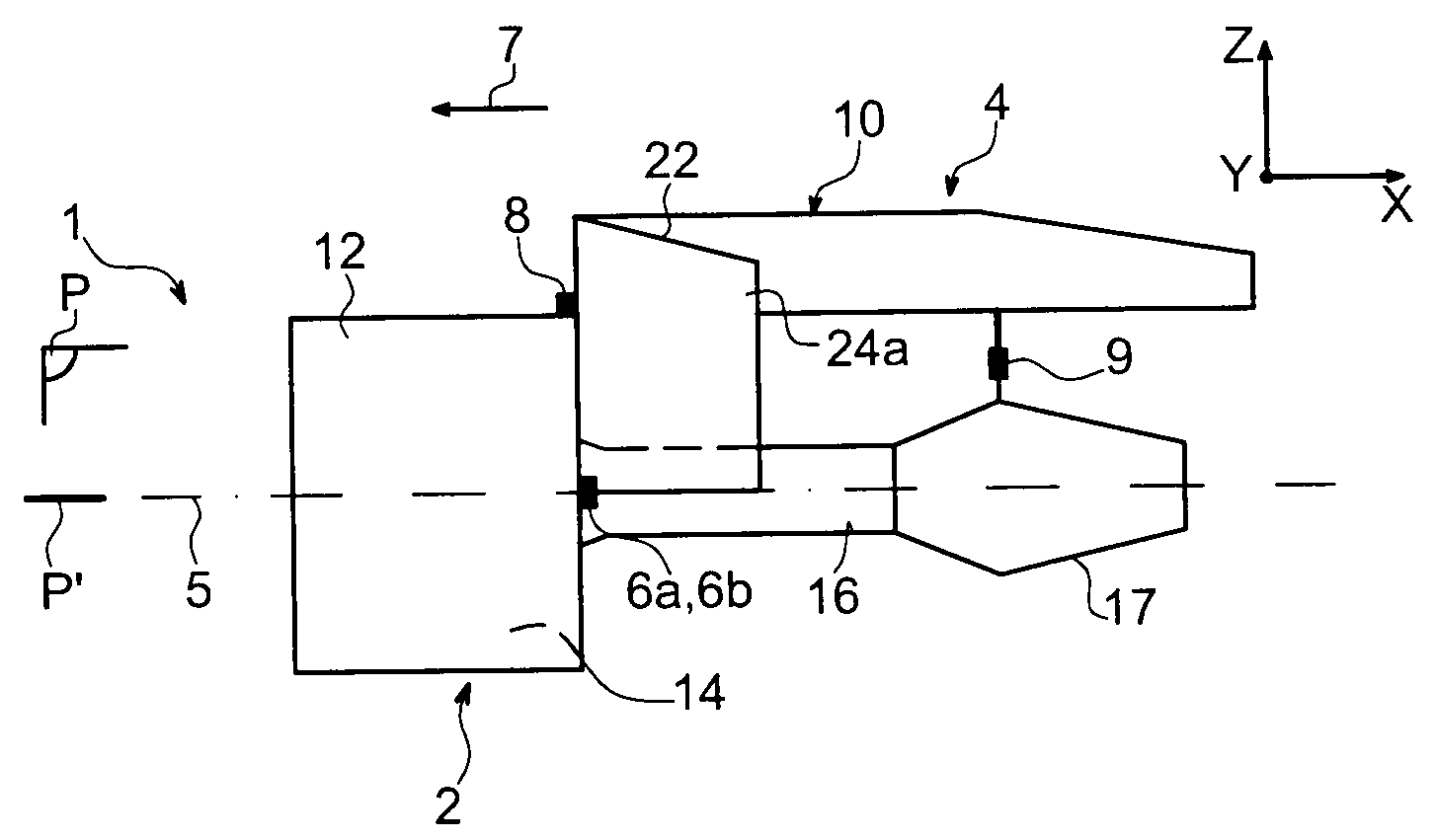
[0056]With reference to FIG. 1, an aircraft engine assembly 1 can be seen intended to be secured below a wing of this aircraft (not shown), this assembly 1 comprising an engine mount 4 according to a preferred embodiment of the present invention.

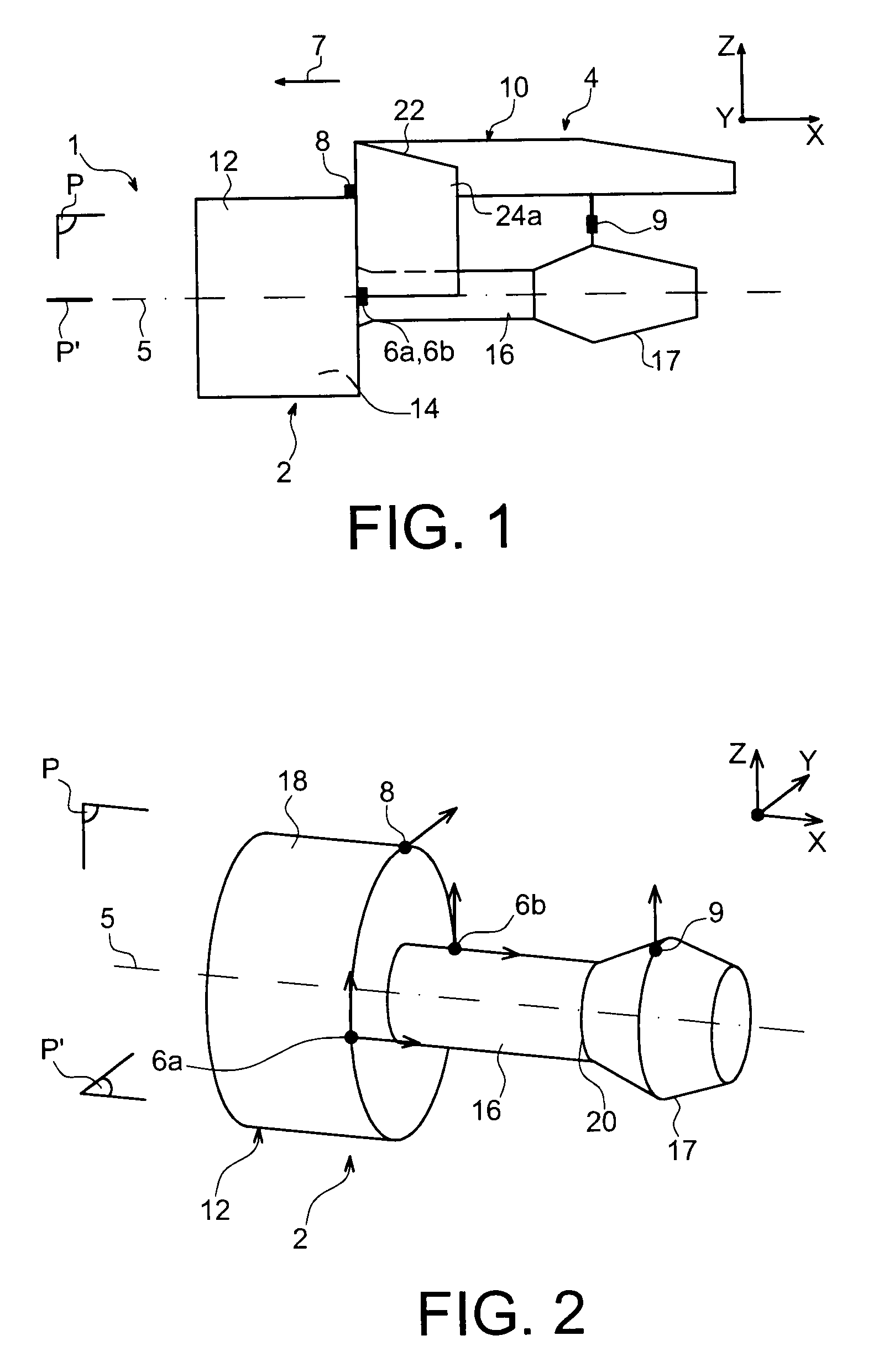
[0057]Globally, the engine assembly 1 consists of a turbojet engine 2 and of the engine mount 4, this mount being provided in particular with a plurality of engine attachments 6a, 6b, 8, 9 and with a rigid structure 10 carrying these same attachments (attachment 6b being masked by attachment 6a in this FIG. 1). It is indicated that the assembly 1 is intended to be surrounded by a nacelle (not shown) and that the engine mount 4 comprises another series of attachments (not shown) to ensure the suspending of this assembly 1 below the aircraft wing.

[0058]In the remainder of the description, by convention, X is used to designate the longitudinal direction of the engine mount 4 which is similar to the longitudinal direction of the turbojet engine ...


PUM


Abstract

A mount for an aircraft turbojet engine. The mount includes a central box formed by an assembly of two side panels joined via transverse ribs and two side boxes secured to a forward part of the box and arranged either side thereof, each side box including an aft closure frame. One of the ribs forming the box includes two side extensions made in a single piece with the rib and respectively projecting from the two side panels outwardly from the box, the two extensions being fixedly mounted on the frame of each of the two side boxes, respectively.

Description

TECHNICAL AREA[0001]The present invention generally relates to a securing pylon for an aircraft turbojet engine. This type of securing pylon, also called <<EMS>> for Engine Mounting Structure, is used to suspend the turbojet engine below the wing of the aircraft, or to mount this turbojet engine above this same wing.STATE OF THE PRIOR ART[0002]Said engine mount is provided to form a connecting interface between a turbojet engine and an aircraft wing. It allows the loads generated by its associated turbojet engine to be transmitted to the airframe, and also provides a path for fuel, electric and hydraulic systems, and air between the engine and the aircraft.[0003]To ensure load transmission, the engine mount comprises a rigid structure, often of <box>> type i.e. formed by the assembly of upper and lower spars and of two side panels joined together via transverse ribs.[0004]Also, the engine mount is provided with a mounting system positioned between the turbojet e...

Claims


Application Information

Patent Timeline
IPC IPC(8): B64D27/00
CPCB64D27/18B64D27/26B64D2027/264Y02T50/44Y02T50/40B64D27/402B64D27/40
Inventor DIOCHON, LIONELCETOUT, JEAN-MICHELLAFONT, LAURENTCHARTIER, DAVID
Owner AIRBUS OPERATIONS (SAS)
Why Eureka
Try Eureka