Interlacing Apparatus, Deinterlacing Apparatus, Display, Image Compressor and Image Decompressor

a technology of interlacing apparatus and deinterlacing equipment, which is applied in the direction of picture reproducers using projection devices, signal generators with optical-mechanical scanning, television systems, etc., can solve the problems of limited interlacing and visible flickering of displayed images, and achieve the effect of easy operation and rapid

Active Publication Date: 2008-07-10
SHARP KK
View PDF4 Cites 20 Cited by
  • Summary
  • Abstract
  • Description
  • Claims
  • Application Information

AI Technical Summary

Benefits of technology

[0030]An embodiment of the present invention provides reconfigurable interlacing apparatus with the advantage that the pixel rearrangement performed by the apparatus can be changed according to the particular requirements of the device or apparatus to which the output image is sent. Reconfiguration of the interlacing apparatus can be performed easily, quickly and as often as is required, and it is possible to use a compact representation for the mapping from pixels of the input images to pixels of the output image. When used to drive a display, the interlacing apparatus is not limited to particular geometries of lenslet, and is capable of performing interlacing at the subpixel level, arbitrarily combining different pixels from different images to form the output image. The reordering can be arranged to match the optical properties of the display.

Problems solved by technology

However, interlacing is limited to combining images at line resolution and the effective reduced update rate of the display results in visible flickering of the displayed images.

Method used


Image

  • Interlacing Apparatus, Deinterlacing Apparatus, Display, Image Compressor and Image Decompressor
  • Interlacing Apparatus, Deinterlacing Apparatus, Display, Image Compressor and Image Decompressor
  • Interlacing Apparatus, Deinterlacing Apparatus, Display, Image Compressor and Image Decompressor

Examples


first embodiment

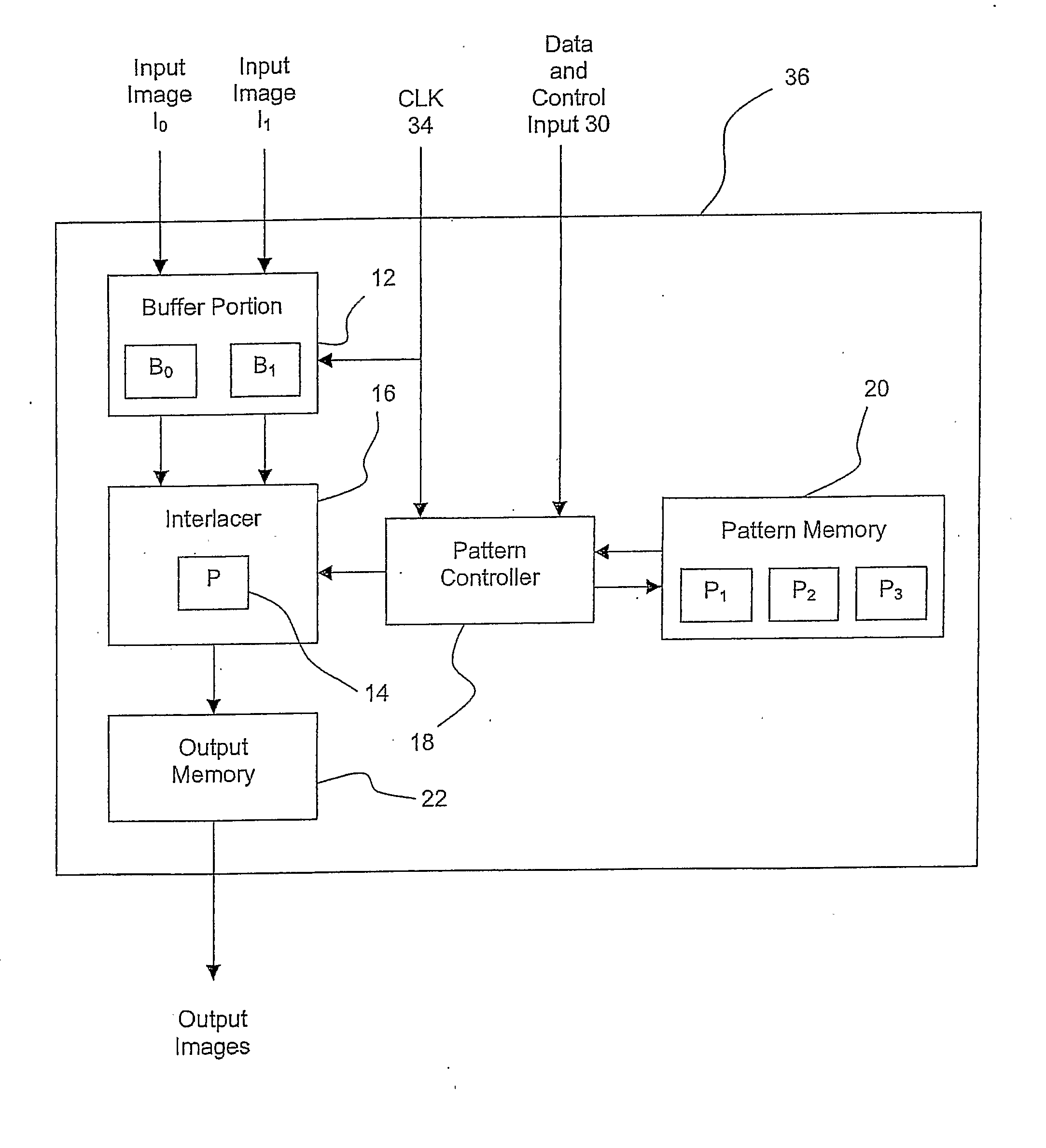
[0050]FIG. 3 is a block diagram illustrating an apparatus 10 for interlacing two input images I0 and I1 to form an output image O. The apparatus 10 comprises a buffer portion 12 including buffers B0 and B1 corresponding to the input images I0 and I1 respectively. The interlacing apparatus 10 also comprises an interlacer, 16 (also referred to herein as a pixel data rearranger) having access to a programmable pattern memory 20, which is shown in FIG. 3 as having stored therein an interlacing configuration pattern P. The interlacer 16 also has a temporary interlacing configuration pattern store 14 for storing the configuration pattern P locally. The interlacing apparatus 10 also comprises an output memory 22.

[0051]In operation of the first embodiment of the present invention, two input images I0 and I1 are received at the interlacing apparatus 10 and buffered in respective buffers B0 and B1 of the buffer portion 12 before being presented to the interlacer 16. Before interlacing commen...

second embodiment

[0062]FIG. 8 is a block diagram illustrating an interlacing apparatus 24 according to the present invention. The second embodiment differs from the first embodiment by including a pattern controller 18 arranged between the interlacer 16 and the pattern memory 20 and having a data and control input 30 for receiving data and control signals from the exterior of the interlacing apparatus 24. In the second embodiment, the pattern memory 20 is also adapted to hold a plurality of interlacing configuration patterns P1, P2 and P3.

[0063]The second embodiment allows the interlacing configuration pattern P used by the interlacer 16 to be changed at any time and replaced by another interlacing configuration pattern from the pattern memory 20 according to the type of interlacing required. Such a change might be triggered, for example, by a control signal received at the data and control input 30 specifying the interlacing configuration pattern to be used. The pattern controller 18 would select t...

third embodiment

[0070]FIG. 11 is a block diagram illustrating interlacing apparatus according to the present invention. The third embodiment differs from the second embodiment in that a time sequence of images to be used to build up an output image is input into the interlacing apparatus 32 via a single input image sequence input. The image data is buffered by the buffer portion 12 before being passed onto the interlacer 16. The third embodiment also differs from the second embodiment in that data output from the interlacer 16 is directly output from the interlacing apparatus 32 without use of the output memory 22 of the second embodiment. Additionally, a clock input is provided, and in use a clock signal CLK presented at the clock input 32 is passed to the pattern controller 18 and to the buffer portion 12.

[0071]In the third embodiment of the present invention, a first image in an input image sequence is received at the interlacing apparatus 32 and buffered in the buffer portion 12. The clock sign...


PUM


Abstract

An apparatus (24) is provided for interlacing a plurality of input images (I0, I1) to form an output image (O). The interlacing apparatus (24) comprises a programmable memory (20) for storing one or more interlacing configuration patterns (P1, P2 and P3) which define a mapping from pixels of the input images (I0, I1) to pixels of the output image (O). The interlacing apparatus (24) also comprises a pixel data rearranger or interlacer (16) for rearranging pixel data in accordance with a pattern (P) stored in the memory (20). A pattern controller (18) is provided for selecting any one of the patterns (P1, P2 and P3) for use in the interlacer (16). Such an interlacing apparatus (24) can be used to drive a display device such as a multiple view directional display device or an autostereoscopic display device. A deinterlacer, an image compressor and an image decompressor are also provided.

Description

TECHNICAL FIELD[0001]The present invention relates to an apparatus for interlacing a plurality of input images to form an output image and to an apparatus for deinterlacing an input image to form a plurality of output images. The present invention also relates to a display including such apparatus and to an image compressor and an image decompressor.BACKGROUND ART[0002]“Field Interlacing” is a well-known technique in television technology and is used to increase the perceived flicker frequency and update rate of a display. In this technique, two “field” images of half the display vertical resolution are combined together to form one “frame”. There is a 180° phase lag between consecutive fields so that one field image comprises odd lines of an original image and the other field image of each frame comprises even lines of the original image at a different time. The process of capturing such images and transferring them to a display as two fields is known as “interlacing” and FIG. 1 of...

Claims


Application Information

Patent Timeline
Patent Type & Authority Applications(United States)
IPC IPC(8): H04N11/20H04N13/00
CPCH04N13/0037H04N13/004H04N19/597H04N13/0409H04N13/0048H04N13/156H04N13/31H04N13/161H04N13/15
Inventor JONES, GRAHAM R.HILL, LYNDON
Owner SHARP KK
Why Eureka
Try Eureka