Measuring technology and computer numerical control technology

a technology applied in the field of measuring technology and computer numerical control technology, can solve the problems of measurement error, reducing efficiency, and reducing the time required for measuremen

Active Publication Date: 2009-03-10
FUJITSU LTD
View PDF5 Cites 22 Cited by
  • Summary
  • Abstract
  • Description
  • Claims
  • Application Information

AI Technical Summary

Benefits of technology

[0029]Therefore, one object of the present invention is to provide a new measuring technique capable of eliminating system errors in a non-contact type optical measurement.
[0030]Another object of the invention is to provide a new measuring technique that can calibrate a measuring unit in the coordinate system of a computer numerical control (CNC) apparatus, which is different in the coordinate system from the measuring unit and can perform a calibration work easily and quickly.
[0031]Still another object of the invention is to provide a new measuring technique that can guarantee the horizontality and flatness in measurement values on a plane if an accidental error is not caused and can reduce the effect of distortion aberration of a lens.

Problems solved by technology

These parameters naturally include measurement errors.
In the light section method, a mechanical moving mechanism of the slit light projection system and the like is required, as described above, so that this causes a bottleneck and presents a problem that time required for measurement can not be shortened to decrease efficiency.
Hence, there is a problem in applying the light section method to a field where the time required for measurement needs to be shortened.
Further, the light section method presents a problem of taking a great deal of time and labor for maintenance and adjustment because it has the mechanical moving mechanism.
These geometrical positions naturally include measurement errors.
As described above, in the fringe pattern projection method, if the fringe wave number is not determined, three-dimensional measurement cannot be performed.
However, the fringe becomes discontinuous in some cases.
In a case where the fringe becomes discontinuous, the continuity of the fringe wave number cannot be used, so that the phase difference cannot be easily calculated.
Further, if the fringe wave number is recognized by mistake, measurement errors are caused.
In the technology like this, only acquisition of the fringe plane equations for the respective fringes is a purpose, so that the relationship between the fringes is not grasped and hence the whole space cannot be expressed correctly.
Hence, correct measured values cannot be obtained in some case.
Hence, in a case where the camera parameters are not calculated with sufficient accuracy, the accuracy of the fringe plane equation is also decreased.
As described above, in the conventional light section method, the measurement errors are included in the parameters necessary for the calculation and restrict measurement accuracy.
However, because the liquid crystal is discrete, it is clear that the degree of the realization of the sine wave fringe has a limitation and hence the measurement accuracy is restricted by this.
Further, while efforts have been made to improve the accuracy of the coefficients of the equation in the conventional method, it is difficult to obtain values with high accuracy for all points in the volume to be measured.
Still further, in the case of “the phase angle fixing type position calculation method”, different points are referenced, but errors are caused by the difference in the brightness on the background of the points referenced, thereby the accuracy is restricted.
In addition, in the fringe pattern projection method, the formula for calculating ΔΦ(and the like shown in the aforementioned papers includes calibration parameters, and these calibration parameters include errors and hence put limitations on accuracy.
Furthermore, there is also presented a problem that in a case where light reception data has system errors, these formulas cannot guarantee the industrially important horizontality of the measured value on the horizontal plane.
The formulas in the aforementioned papers guarantee the horizontality only for the reference plane if accidental errors are not caused but do not guarantee the horizontality for the horizontal planes of the other heights.
Further, each of a fringe pattern projection lens and a fringe pattern taking lens has distortion aberration.
For example, when an object of 200 mm in width is measured by use of a lens having a distortion aberration of 0.5%, an error of 1.0 mm is caused by the distortion aberration.
Although measurement can be compensated to some extent by calculation, it is clear that there is a limitation on the compensation by the calculation.
The problem of the distortion aberration is ditto for the light section method.
However, when a measuring unit is mounted on a NC (numerical control) machine tool and measurement is performed and the NC machine tool is controlled by use of the measured data, the axis of the measuring unit does not agree with the axis of the machine tool, which causes errors.
Still further, conventionally, a high technique and a long time are required to calibrate the parameters of the measuring unit with high accuracy and hence a request of recalibration requiring high accuracy is usually made to a manufacturer of the measuring unit.
In the case of using the measuring unit in the manufacture of products, there is presented an economic problem such as manufacture shutdown.
A method has not been known by which anybody can easily perform calibration in a short time without any particular technique.

Method used


Image

  • Measuring technology and computer numerical control technology
  • Measuring technology and computer numerical control technology
  • Measuring technology and computer numerical control technology

Examples


first embodiment

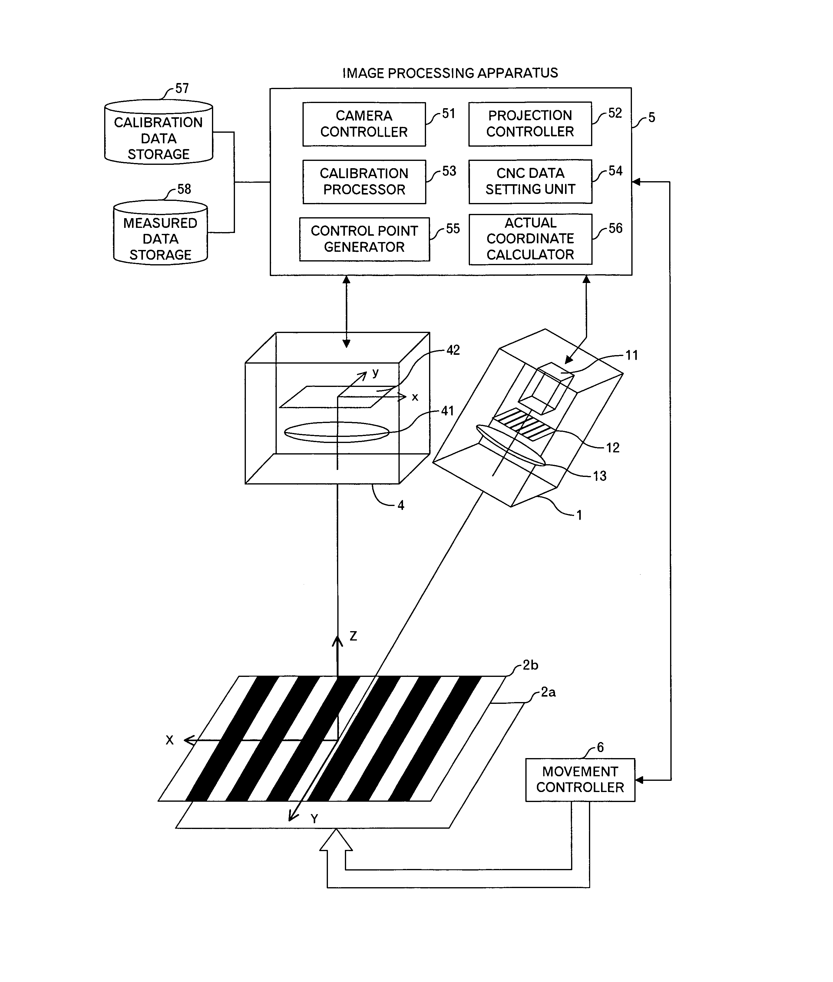
[0090]FIG. 4 shows a functional block diagram in the first embodiment of the present invention using a fringe pattern projection method. A CNC apparatus (for example, a machine tool, but it is not intended to limit the CNC apparatus to the machine tool) including a measuring apparatus in this embodiment has: an image processing apparatus 5 that performs a main processing in this embodiment and is a computer; a liquid crystal projector 1 that is connected to the image processing apparatus 5 and has a projection unit 11 such as a lamp, a liquid crystal panel 12 forming a grating, and a lens 13; a camera 4 that is connected to the image processing apparatus 5 and has a lens 41, a CCD 42, and a memory (not shown); a reference plane 2 that is a reference plane at the time of calibration (however, it is assumed that a reference plane for height Z=Z1 is indicated as the reference plane 2a and that a reference plane for height Z=Z2 is indicated as the reference plane 2b); and a movement con...

second embodiment

[0165]Next, the configuration in a case of using the light section method will be described with reference to FIGS. 23 to 29. First, FIG. 23 shows a functional block diagram. A CNC apparatus including a measuring unit in this embodiment includes a image processing apparatus 2305 that performs a main processing in this embodiment and is a computer, a measurement unit 2330 having a projection unit 2301 that is connected to the image processing apparatus 2305 and projects slit light and a camera 2304, a reference plane 2302 that is used as a reference plane (where, it is assumed that a reference plane for height Z=Z1 is denoted by 2302a and that a reference plane for Z=Z2 is denoted by 2302b) at the time of calibration, and a movement controller 2306 that is connected to the image processing apparatus 2305 and controls movement at least in a Z direction of the reference plane 2302. The projection unit 2301 has a light source 2311 such as laser light source and a slit 2312. Further, the...


PUM


Abstract

A measuring apparatus of this invention comprises: a projector; a camera; a generator that generates, from a photographed image of a fringe pattern projected by the projector at a time of calibration onto each of surfaces, first tuples, each including coordinates of a point on a light receiving plane (LRP) of the camera, light intensity of the point and the height of the surface; a converter that converts the light intensity to a phase angle of the projected fringe pattern (PFP), and generates second tuples, each including the coordinates of the point on the LRP, the phase angle and the height of the surface; a hypersurface generator that generates data representing a tensor product type composite hypersurface (TPTCH) from data of the second tuples; an extractor that extracts data of third tuples, each including coordinates of a point on the LRP and light intensity from a photographed image of a fringe pattern projected by the projector at a time of measurement onto an object to be measured; a second converter that converts the light intensity to a phase angle of the PFP to generate data of fourth tuples, each including the coordinates of the point on the LRP and the phase angle; and an interpolator that carries out interpolation by using the data representing the TPTCH to generate height data corresponding to the data of the fourth tuple.

Description

TECHNICAL FIELD OF THE INVENTION[0001]The present invention relates to a technique to measure the three-dimensional shape of an object to be measured by projecting light to the object to be measured.BACKGROUND OF THE INVENTION[0002]The measurement of a three-dimensional shape has been used not only in an industrial field but also in social various fields such as medicine, biology, archaeology, and the examination and restoration of works of art. In the three-dimensional measurement, non-contact type optical measurement has been more desired than conventional contact type measurement. Region measurement in the optical measurement is broadly divided into a light section method of measuring a region by scanning the region with one linear slit light in a direction perpendicular to a direction of slit and a measurement method of measuring a region by a surface.[0003]As for the light section method, although various modes have been developed, it is basically based on a principle shown in ...

Claims


Application Information

Patent Timeline
Patent Type & Authority Patents(United States)
IPC IPC(8): G01B11/24G01B11/25
CPCG01B11/2527G06T7/0057G06T7/521
Inventor SUZUKI, TATSUHIKO
Owner FUJITSU LTD
Why Eureka
Try Eureka