Plasma display device and method of driving the same

a display device and plasma technology, applied in the field of display devices, can solve the problems of flicker still not being responded, display quality problems problem (flicker) not being sufficiently responded, so as to prevent flicker generation, reduce or prevent flicker generation, and ensure or improve display quality

Inactive Publication Date: 2008-12-25
MAXELL HLDG LTD
View PDF5 Cites 4 Cited by
  • Summary
  • Abstract
  • Description
  • Claims
  • Application Information

AI Technical Summary

Benefits of technology

[0013]In view of the above problems, a main object of the present invention is to provide a technique capable of suppressing or preventing generation of flicker (blink) caused by a sustain period control (i.e., increasing or decreasing change in sustain period (subfiel...

Problems solved by technology

The variation in weighted emission center position becomes a cause of generation of flicker (blink) etc. in the screen (PDP display region) and it will be problematic in display quality.
The variation in weighted emission center position (G) of the field is small compared to that when the subfields are arranged without the gap, but the weighted emission center position of each subfield still varies due to increase and decrease in th...

Method used


Image

  • Plasma display device and method of driving the same
  • Plasma display device and method of driving the same
  • Plasma display device and method of driving the same

Examples


first embodiment

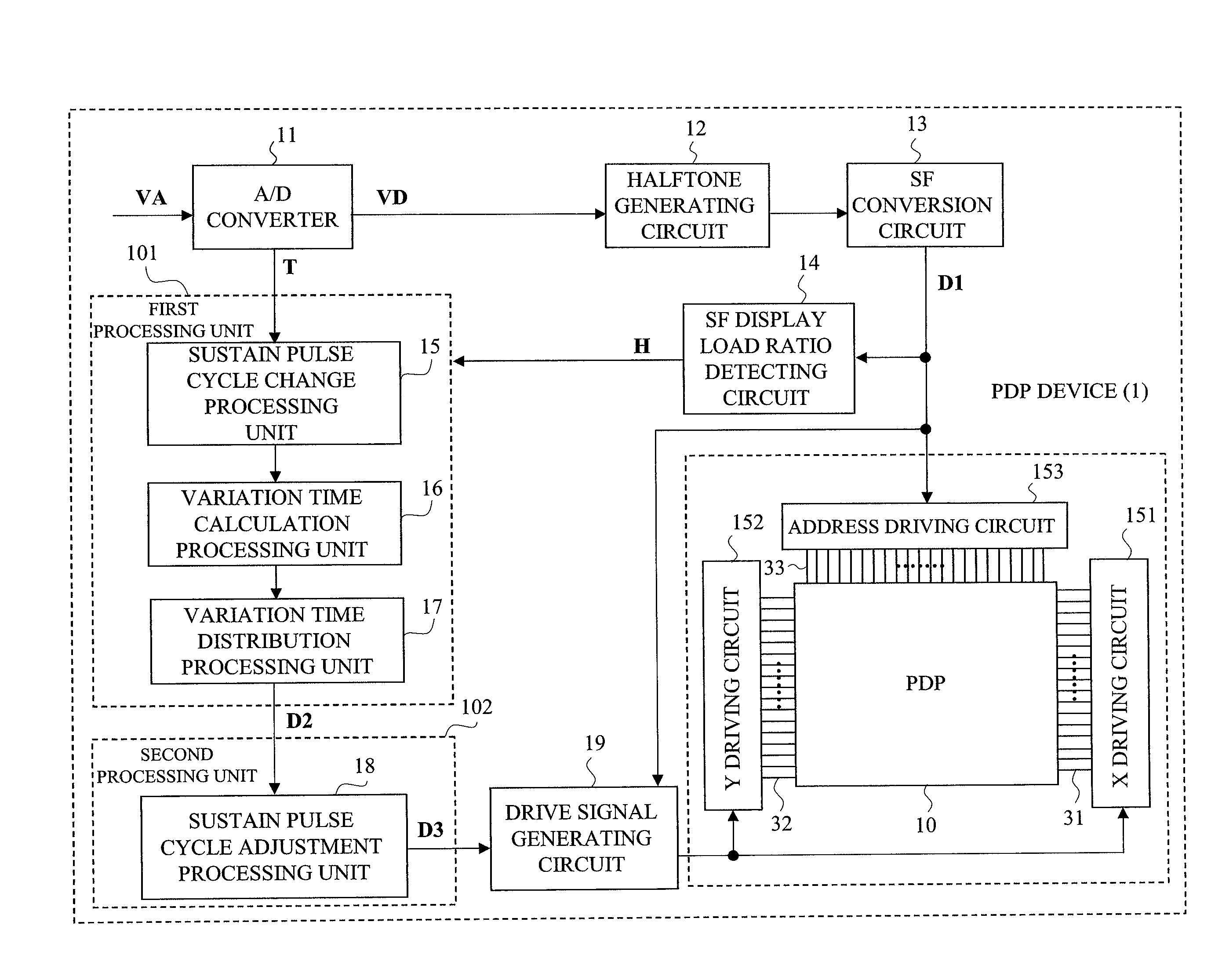
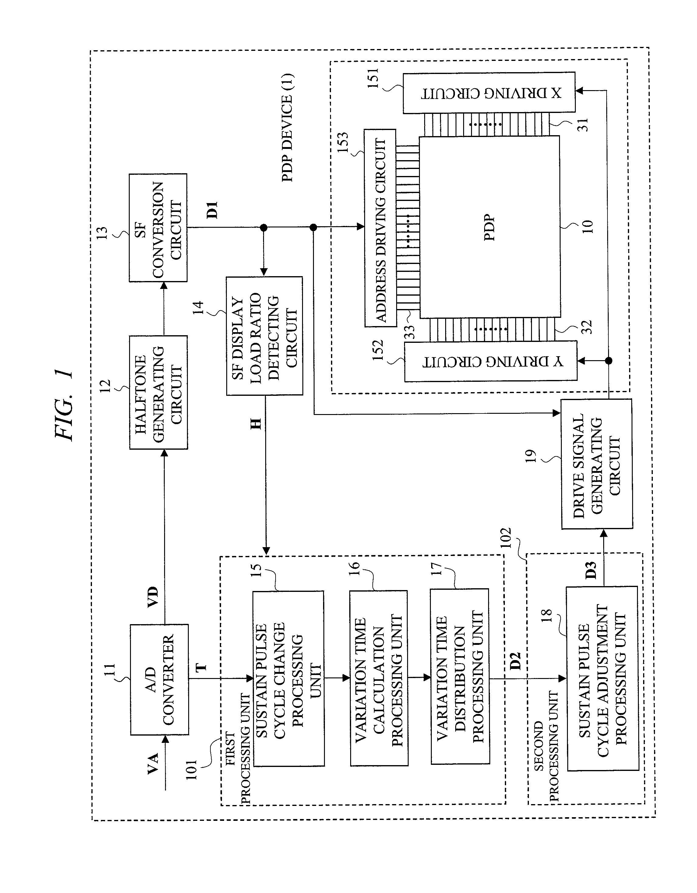
[0036]A PDP device of a first embodiment of the present invention will be described with reference to FIG. 1 to FIG. 7. As an outline, in the PDP device having a function of sustain period control by a sustain pulse cycle (C) control, along with a process of the cycle (C) control (first process), a process for adjusting sustain pulse cycle (C) (second process, also referred to as control of sustain pulse cycle (c) combination) in which a combination of sustain pulses of one or more than one sustain pulse cycle (C) is selected to configure a sustain period based on the display load ratio (H) of an SF and the like is performed in the first embodiment. According to such process (second process), an adjustment is made between previous and subsequent fields to have timing (temporal position) of the field and each SF and the like almost the same, so that respective weighted emission center positions are almost the same.

[0037]

[0038]FIG. 1 shows a block configuration of the PDP device of th...

second embodiment

[0088]Next, a PDP device of a second embodiment of the present invention will be described with reference to FIG. 8 and FIG. 9. The second embodiment has a basic configuration similar to that of the first embodiment, and the following (A) and (B) controls are performed with respect to display of a field group as a control to be added to the control of the first embodiment (sustain pulse cycle (C) combining control).

[0089]First, in the (A) first control, presence of scene change is detected as the image content (outline) according to the APL differential value between image frames (f), where the control of the first embodiment is turned OFF (not applied) when scene change is found, and the control of the first embodiment is turned ON (applied) when scene change is not found. The (A) first control prioritizes the variation in luminance and weighted emission center position that obviously exist in the original image content.

[0090]Further, when turning ON the control of the first embodi...

third embodiment

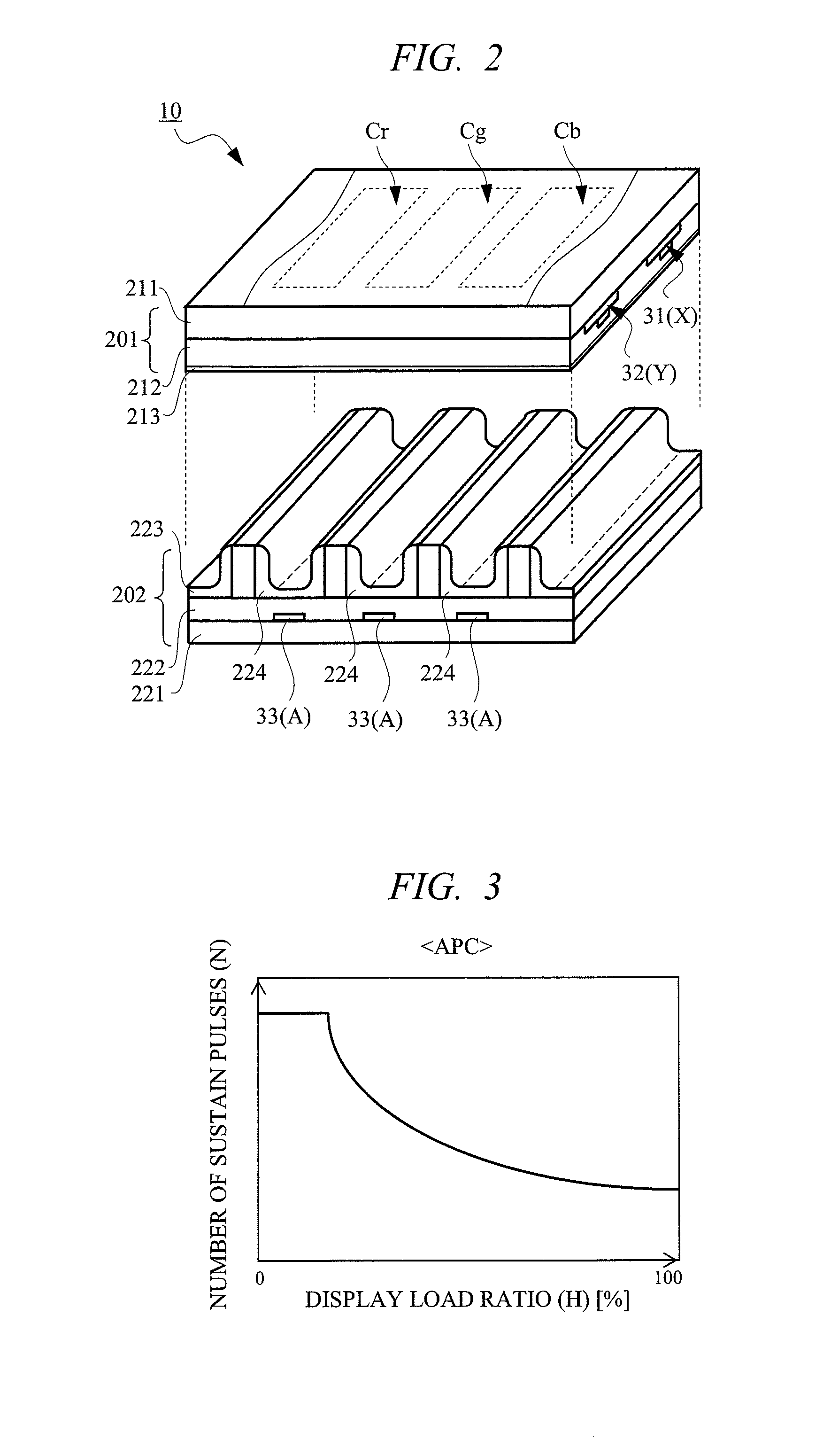
[0099]A PDP device of a third embodiment will be described with reference to FIG. 10. In the third embodiment, a configuration including an APC processing unit 104 without the first processing unit 101 is adopted. The APC processing unit 104 includes a number (N) of sustain pulses change processing unit 25 in addition to the SF display load ratio (H) detecting circuit 14. The APC process is similar to those in FIG. 3 and FIG. 4, and the change of cycle (C) is not performed.

[0100]In the APC processing unit 104, the display load ratio (H) of the SF is calculated by the SF display load ratio detecting circuit 14 based on the display data (D1). The N change processing unit 25 computes the number (N) of sustain pulses etc. of each SF as information necessary for the APC based on the information of the display load ratio (H) of the SF. For instance, the larger the display load ratio (H) of the SF is, the smaller the number (N) of sustain pulses of Ts 73 is. Thus, the APC processing unit 1...


PUM


Abstract

A technique capable of suppressing or preventing generation of flickers (blinks) by a sustain period control as well as capable of ensuring or enhancing display quality in a PDP device. The PDP device adjusts a sustain pulse of the sustain period for every subfield by selecting a combination of one or more than one cycle so that start and end timings of a field in fields before and after change are almost the same according to a display load ratio of the subfield of the field. Field weighted emission center positions then becomes almost the same, and flickers and the like are suppressed.

Description

CROSS-REFERENCE TO RELATED APPLICATION[0001]The present application claims priority from Japanese Patent Application No. JP 2007-163293 filed on Jun. 21, 2007, the content of which is hereby incorporated by reference into this application.TECHNICAL FIELD OF THE INVENTION[0002]The present invention relates to a display device for performing a multiple grayscale display using a sub-field method (frame time division display method) of a plasma display device (PDP device) and the like comprising a plasma display panel (PDP). More particularly, the present invention relates to a configuration of a field (field period) and a subfield (subfield period).BACKGROUND OF THE INVENTION[0003]In a PDP device, an auto power control (APC) for changing the number (N) of sustain pulses of a subfield and adjusting the luminance and the power of display according to a display load ratio (H) of an image (display data) and the like and a control (hereinafter, referred to as sustain pulse cycle (C) control...

Claims


Application Information

Patent Timeline
IPC IPC(8): G09G3/18G09G3/291G09G3/20G09G3/28G09G3/288G09G3/294G09G3/298
CPCG09G3/2044G09G3/2059G09G3/2944G09G3/2946G09G2320/02G09G2360/16G09G3/296
Inventor TAKEUCHI, MASANORIUEDA, TOSHIO
Owner MAXELL HLDG LTD
Why Eureka
Try Eureka