Motion estimation with adaptation of the correlation block size
a technology of correlation block and motion estimation, which is applied in the field of motion estimation with adaptation of the size of the correlation block, can solve the problems of hardware and/or processing capacity cost, and achieve the effects of smoothing the variation in the size of the block, facilitating a precise and facilitating the determination of the normal motion vector
- Summary
- Abstract
- Description
- Claims
- Application Information
AI Technical Summary
Benefits of technology
Problems solved by technology
Method used
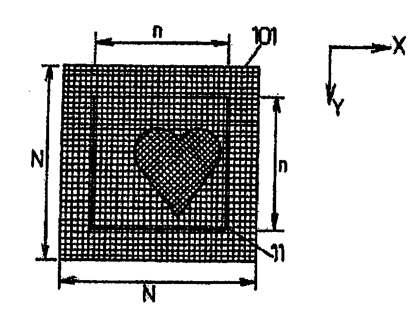
Image

Examples
Embodiment Construction
[0055]Embodiments are particularly described in how they apply to motion detection for the optical mouse. It is possible to deduce an application for any system in which an image sequence is processed in order to detect the motion of a mobile sensor relative to a fixed point of reference.
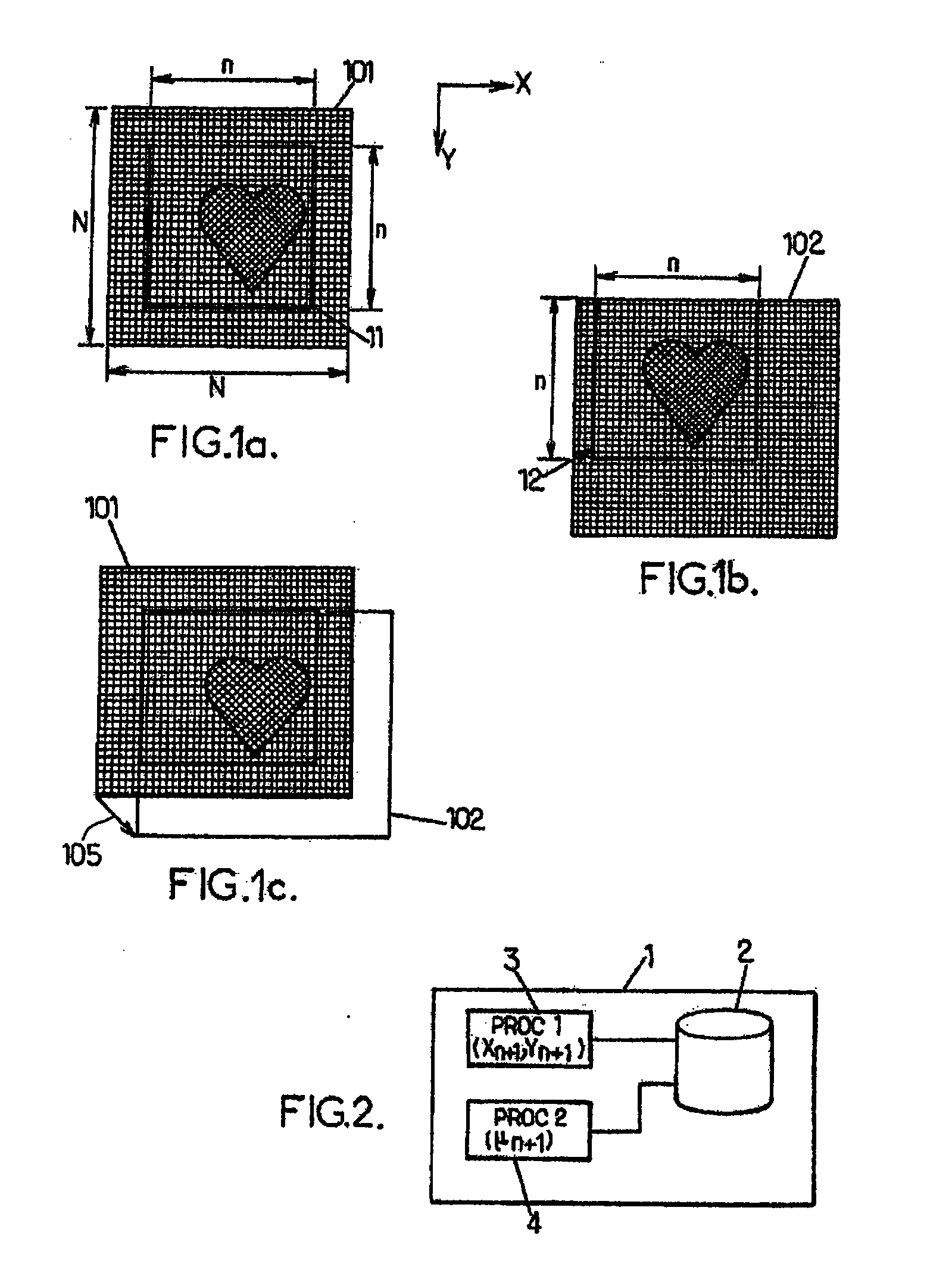
[0056]FIG. 2 represents a motion determination module 1 in one embodiment, comprising a memory 2, a correlation block dimension generator or module 3 for implementing a first process Proc1, and a motion vector generator or module 4 for implementing a second process Proc2. This process Proc2 is based on the principles of a process as described in the patent application FR0507167.
[0057]In one embodiment, the module 1 is carried by the optical mouse, similarly to the mobile sensor.
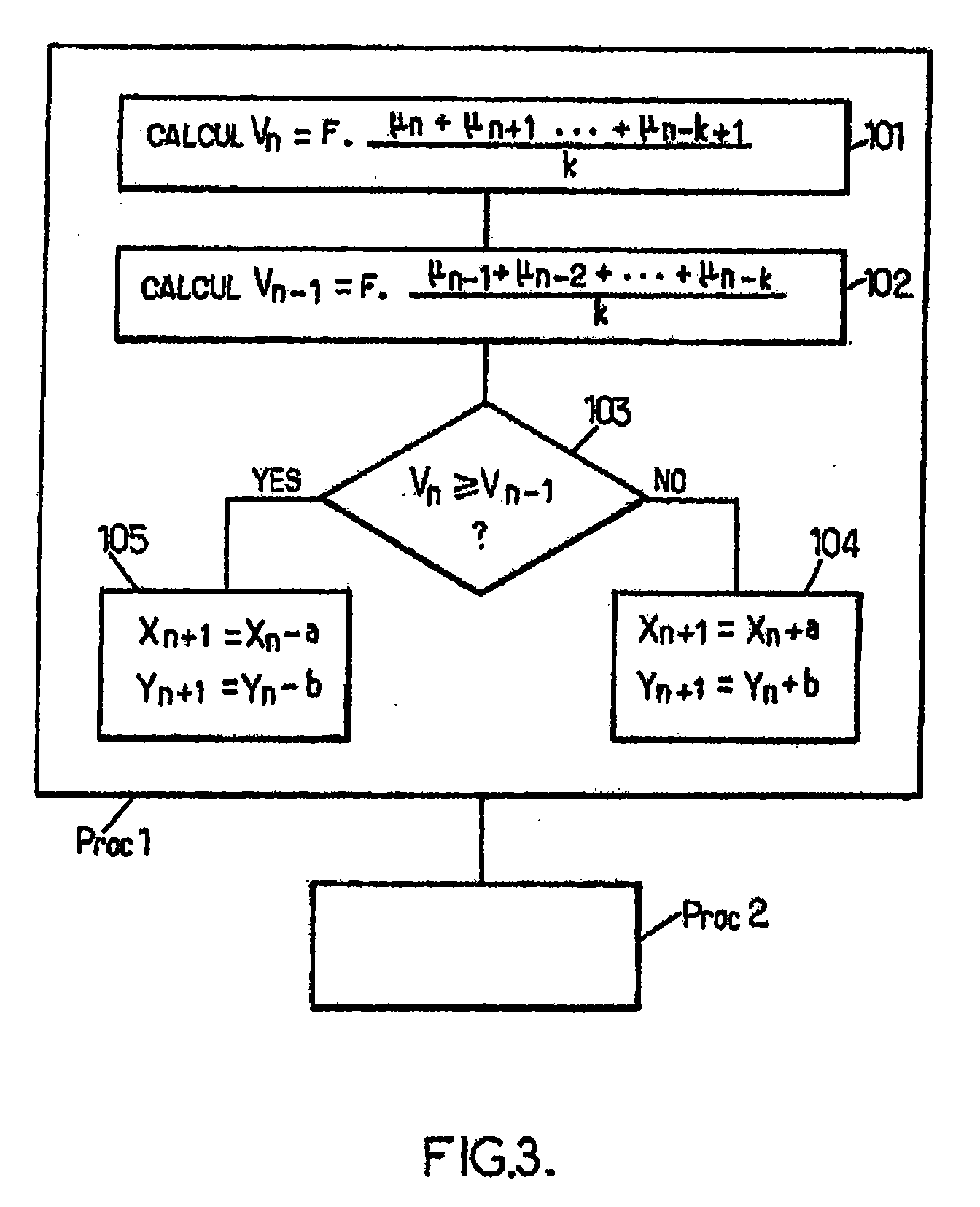
[0058]FIG. 3 illustrates the main steps of a displacement determination process according one embodiment.
[0059]These steps can be applied for each image captured by the sensor incorporated into the mouse. This is the case con...
PUM
 Abstract
Description
Claims
Application Information