Die Cut Insulation Blanket

a technology of insulation blankets and die cuts, applied in the direction of cellulosic plastic layered products, paper/cardboard articles, manufacturing tools, etc., can solve the problems of increasing the friability of materials, reducing the strength and integrity of resulting materials, and the number of fiber-to-fiber bonds

Active Publication Date: 2008-12-25
OWENS CORNING INTELLECTUAL CAPITAL LLC
View PDF70 Cites 13 Cited by
  • Summary
  • Abstract
  • Description
  • Claims
  • Application Information

AI Technical Summary

Benefits of technology

[0013]In the following description there is shown and described several possible embodiments of the present invention, simply by way of illustration of some of the modes best suited to carry out the invention. As it will be realized, the invention is capable of other different embodiments and its several details are capable of modification in various, obvious aspects all without departing from the invention. Accordingly, the drawings and descriptions will be regarded as illustrative in nature and not as restrictive.

Problems solved by technology

Unfortunately, the stretching of the material to open the honeycomb or cellular structure leads to the tearing of a significant number of the fiber-to-fiber bonds thereby reducing the strength and integrity of the resulting material.
Further, the tearing of so many bonds also increases the friability of the material.
Thus, erection of the honeycomb web or cellular material in accordance with prior art methods leads to two significant detrimental results.

Method used


Image

  • Die Cut Insulation Blanket
  • Die Cut Insulation Blanket
  • Die Cut Insulation Blanket

Examples


first embodiment

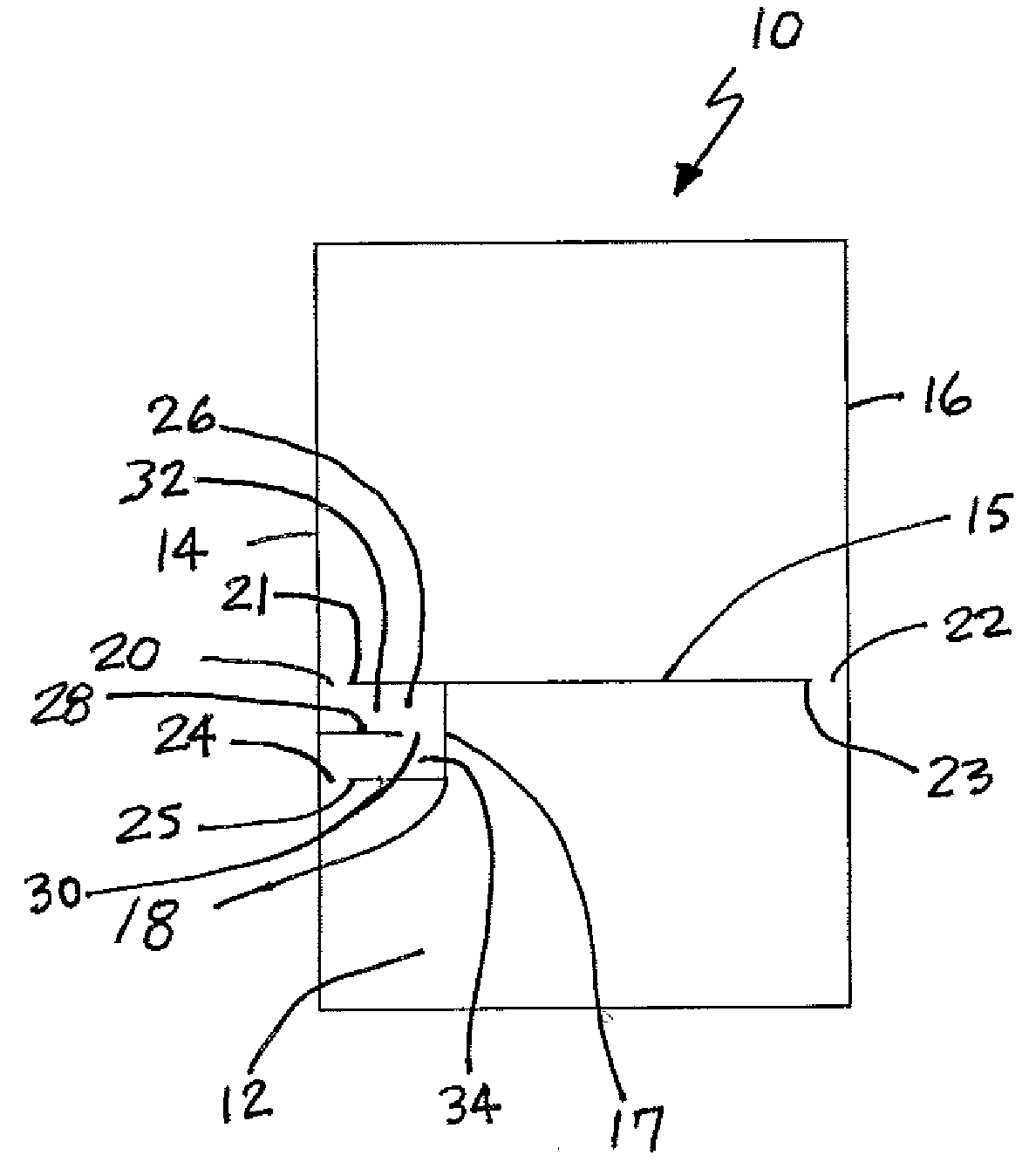
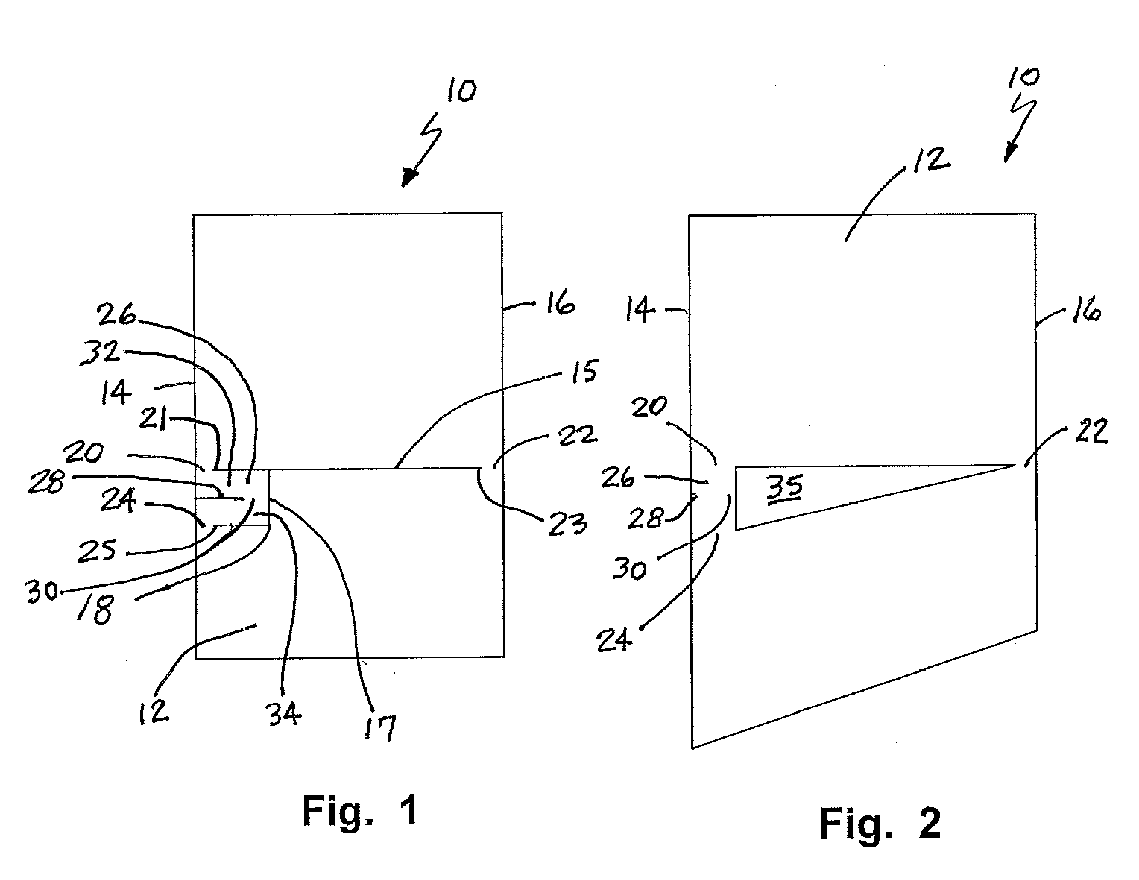
[0022]Reference is now made to FIG. 1 illustrating the insulation blanket 10 of the present invention. As shown the insulation blanket 10 includes a body 12 formed from an insulation material. The body 12 includes a first edge 14 and a second edge 16 wherein the first and second edges 14, 16 are provided opposite one another.

[0023]A typical material useful in the construction of the insulation blanket 10 of the present invention is a non-woven synthetic material, a non-woven natural material and mixtures thereof. The material may include thermoplastic fiber material, thermosetting fiber material, bicomponent fiber material and mixtures thereof. Various polymers are particularly useful in the present invention. Still more specifically the material may be selected from a group consisting of polyolefin, polypropylene, polyethylene, polyester, nylon, rayon, polyethylene terephthalate, polybutylene terephthalate, cotton, kenaft silk, cellulose, hemp, jute, sisal, shoddy and mixtures ther...

second embodiment

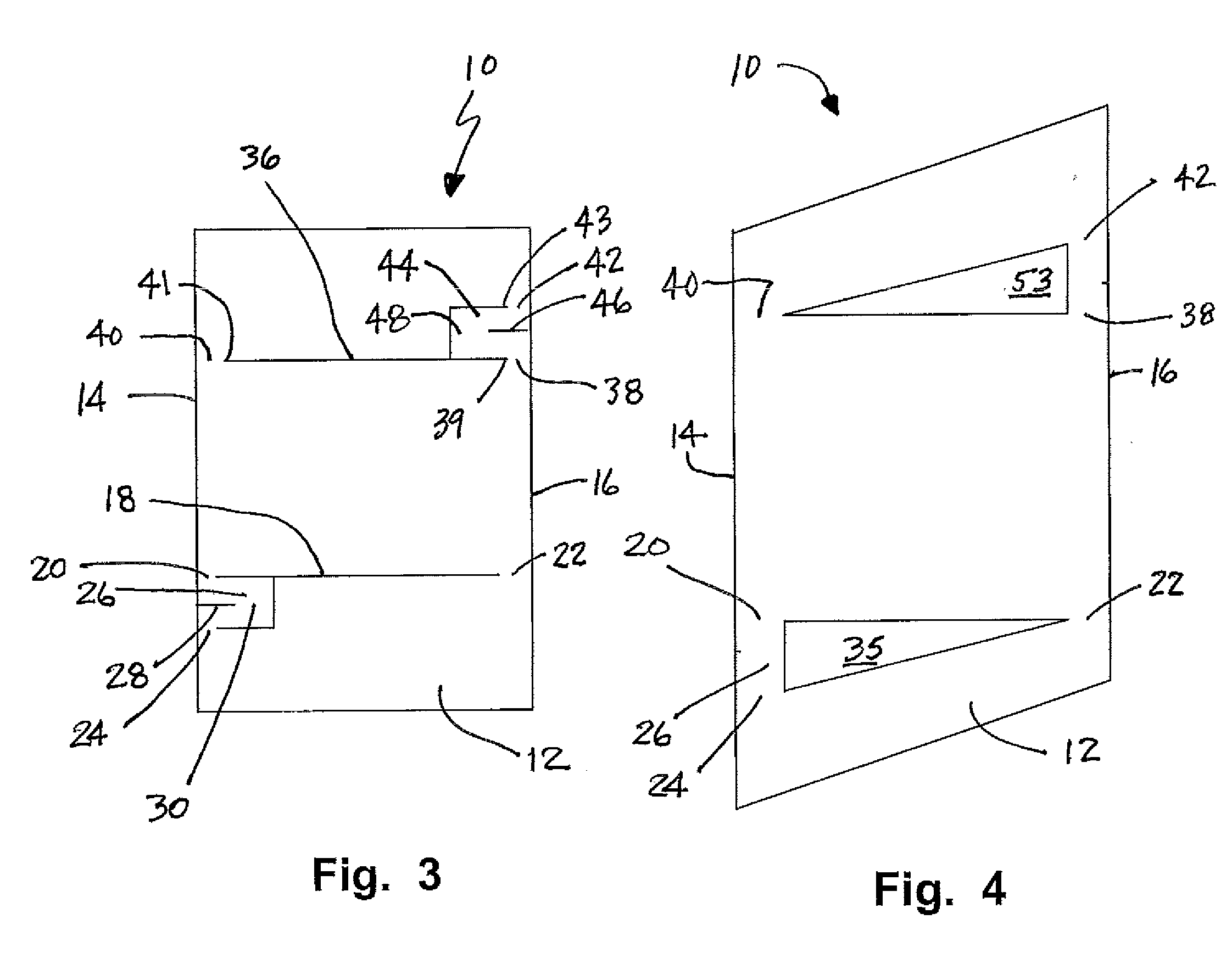
[0028]the expandable insulation blanket 10 is illustrated in FIGS. 3 and 4. As illustrated in FIG. 3, the insulation blanket 10 includes all of the structures illustrated in the FIG. 1 embodiment and each of those structures is labeled with an identical reference number. In addition, the insulation blanket 10 illustrated in FIG. 3 includes a third slit 36 that is substantially h-shaped. The third slit 36 defines a fifth hinge point 38 between a first end 39 of the third slit 36 and the second edge 16, a sixth hinge point 40 between a second end 41 of the third slit 36 and the first edge 14 and a seventh hinge point 42 between a third end 43 of the third slit and the second edge. A second hinge body 44 is outlined by the third slit 36, the fifth hinge point 38 and the seventh hinge point 42. A fourth slit 46 extends across the second hinge body 44 and defines an eighth hinge point 48 between the fourth slit 46 and the third slit 36.

[0029]The second embodiment of the insulation blanke...


PUM

PropertyMeasurementUnit
lengthaaaaaaaaaa
diameteraaaaaaaaaa
perimeter areaaaaaaaaaaa

Abstract

An expandable insulation blanket includes a body of insulation material having a first edge and a second edge wherein the first and second edges are opposite one another. A first slit defines a first hinge point between a first end of the first slit and the first edge, a second hinge point between a second end of the first slit and the second edge and a third hinge point between a third end of the first slit and the first edge. A first hinge body is outlined by the first slit, the first hinge point and the third hinge point. A second slit extends across the first hinge body and defines a fourth hinge point between the second slit and the first slit. When expanded the insulation body includes a substantially triangular shaped opening.

Description

[0001]This application is a continuation-in-part of prior U.S. patent application Ser. No. 11 / 209,005 filed on 22 Aug. 2005.TECHNICAL FIELD AND INDUSTRIAL APPLICABILITY OF THE INVENTION[0002]The present invention relates generally to a die cut insulation blanket that may be made utilizing less material per unit of perimeter area.BACKGROUND OF THE INVENTION[0003]Perforated non-woven fabrics of polymer material are well known in the art, Representative examples include U.S. Pat. Nos. 5,714,107 to Levy et al., 4,615,671 to Bemal and 3,864,198 to Jackson. In each of these prior art patents the polymer material is slit or cut and then subjected to stretching to provide a honeycomb web or open cell structure.[0004]Unfortunately, the stretching of the material to open the honeycomb or cellular structure leads to the tearing of a significant number of the fiber-to-fiber bonds thereby reducing the strength and integrity of the resulting material. Further, the tearing of so many bonds also in...

Claims


Application Information

Patent Timeline
Patent Type & Authority Applications(United States)
IPC IPC(8): B32B3/02
CPCB31D1/00B31D3/002B31D3/0223Y10T428/254Y10T428/236Y10T428/24149Y10T428/24777Y10T428/237Y10T428/23
Inventor ROCKWELL, ANTHONY L.
Owner OWENS CORNING INTELLECTUAL CAPITAL LLC
Why Eureka
Try Eureka