
Patient-matched surgical component and methods of use

Inactive Publication Date: 2008-12-25
BIOMET MFG CORP
View PDF100 Cites 166 Cited by
  • Summary
  • Abstract
  • Description
  • Claims
  • Application Information

AI Technical Summary

Benefits of technology

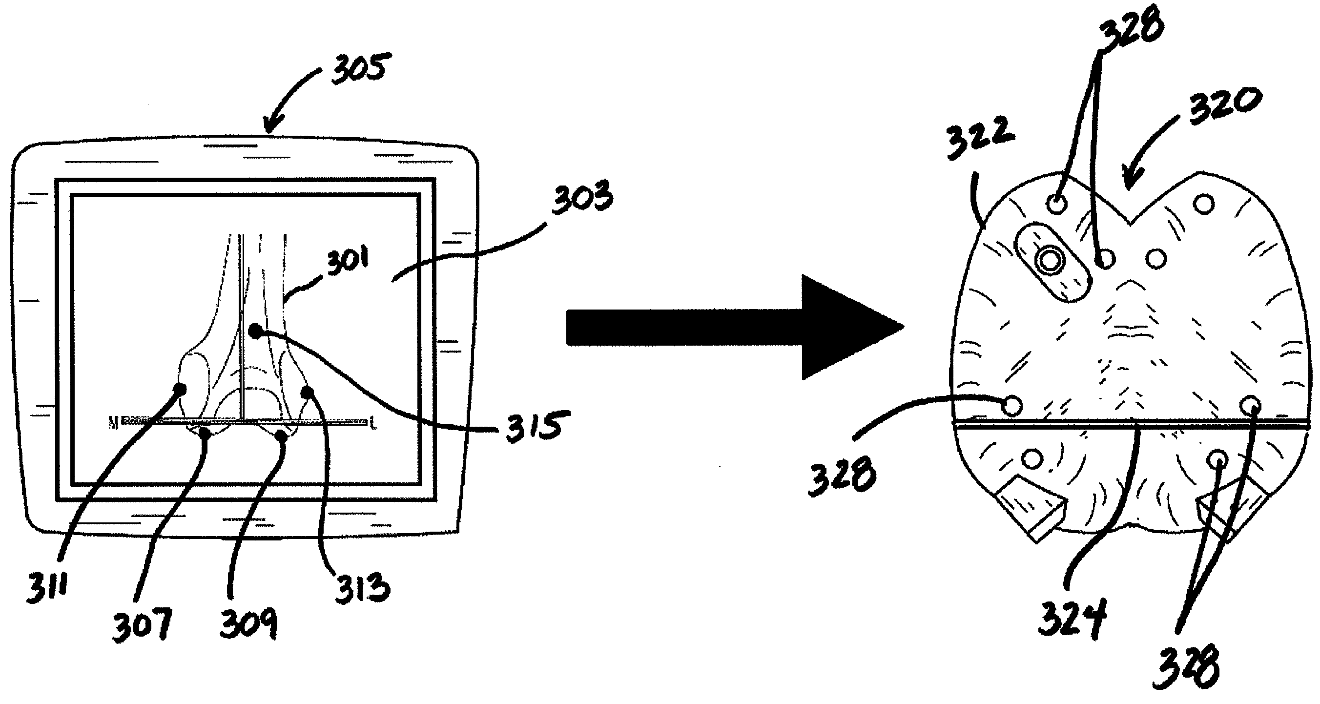
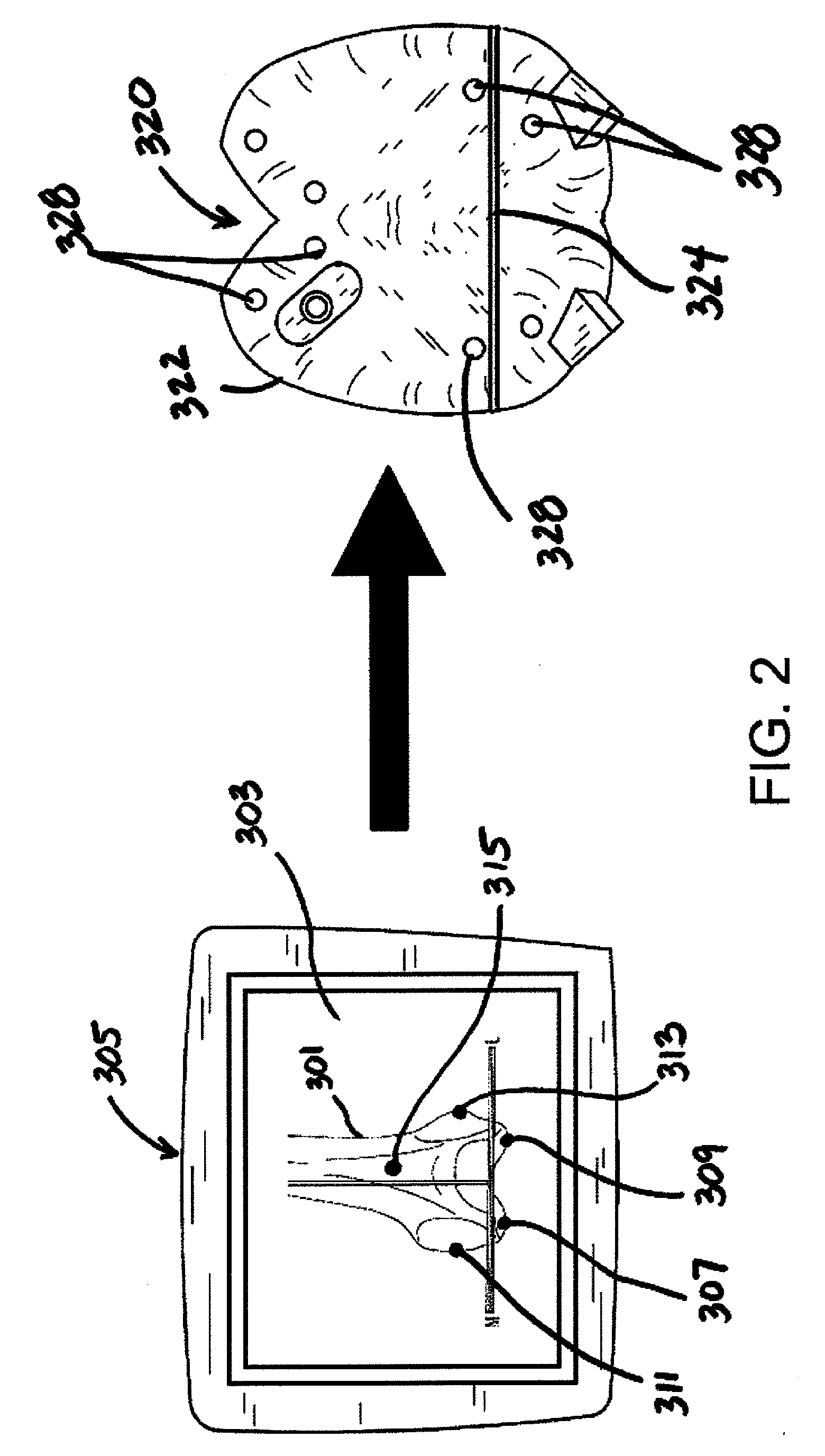
[0007]The present teachings provide a patient matched surgical component that is custom manufactured to fit a patient's anatomy in a precise manner. To achieve such customization, the patient's anatomy is preoperatively scanned and uploaded to a software program, which then recreates a three-dimensional model of the patient's anatomy from the scanned image. The three-dimensional model is then used by the software program to identify and locate on the image specific known anatomical landmarks of the patient's anatomy. Planning software then analyzes the identified anatomical landmarks together with any specific surgical instructions needed to develop and plan a surgical protocol for the patient. Once the surgical protocol has been approved by the surgeon, the protocol is presented to a software program, which then uses the protocol, as well as the preoperative scan images, to create a virtual patient matched surgical component. The virtual component is then sent to a rapid prototyping machine or a standard machining process, which in turn manufactures the surgical component for use during the surgical procedure. Because the surgical component is custom manufactured to fit the patient's anatomy relative to specific anatomical landmarks, it can be manufactured with a reference array positioned on its surface in a predefined spatial relationship with respect to the patient's anatomy. By having a predefined spatial relationship between the reference array and the patient's anatomy, the need for intra-operative registration during the surgical procedure is minimized or even eliminated altogether. Furthermore, since the patient matched component is fixable to the patient's anatomy with pins, the reference array can act as an automatically registered rigid bone reference marker that can be used throughout the surgical navigation procedure.

Problems solved by technology

However, this process is time consuming, as well as subject to error during the placement and registration of the surgical components.

Method used


Image

  • Patient-matched surgical component and methods of use
  • Patient-matched surgical component and methods of use
  • Patient-matched surgical component and methods of use

Examples


Embodiment Construction

[0024]The embodiments of the present teachings described below are not intended to be exhaustive or to limit the invention to the precise forms disclosed in the following detailed description. Rather, the embodiments are chosen and described so that others skilled in the art may appreciate and understand the principles and practices of the present teachings.

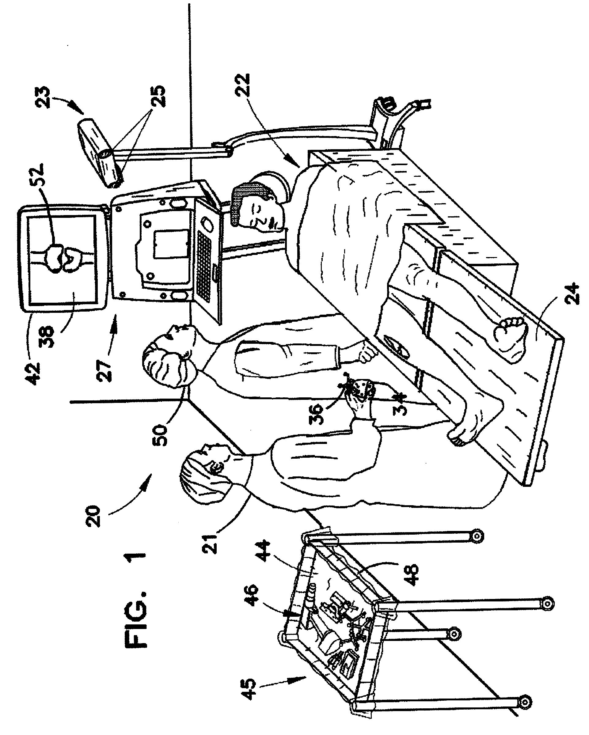
[0025]FIG. 1 shows a perspective view of an operating room with surgical navigation system 20. Surgeon 21 is aided by surgical navigation system 20 in performing knee arthroplasty, also known as knee replacement surgery, on patient 22 shown lying on operating table 24. Surgical navigation system 20 has a tracking system that locates arrays and tracks them in real-time. To accomplish this, the surgical navigation system includes optical locator 23, which has two CCD (charge couple device) cameras 25 that detect the positions of the arrays in space by using triangulation methods. The relative location of the tracked arrays, includi...


PUM


Abstract

A method of automatically registering a surgical navigation system to a patient's anatomy is provided. The method comprises programming a surgical navigation system with a first spatial relationship between a surgical component and a reference array connected to the surgical component, programming the surgical navigation system with a second spatial relationship between an anatomical feature of a patient and the surgical component, installing the surgical component on the patient such that the surgical component engages the anatomical feature in the second spatial relationship, and locating the reference array with the surgical navigation system. The navigation system automatically recognizes the position of the reference array relative to the patient's anatomy.

Description

RELATED APPLICATIONS[0001]This application claims the benefit of U.S. Provisional Patent Application Ser. No. 60 / 944,817, filed Jun. 19, 2007, the complete disclosure of which is expressly incorporated herein by this reference.FIELD OF THE INVENTION[0002]The present teachings relate generally to surgical navigation, and more particularly to patient-matched surgical components that are adapted to conform to a patient's anatomy, as well as to methods for using such surgical components during a surgical navigation procedure.BACKGROUND[0003]Surgical navigation systems, also known as computer assisted surgery systems and image guided surgery systems, aid surgeons in locating patient anatomical structures, guiding surgical instruments, and implanting medical devices with a high degree of accuracy. Surgical navigation has been compared to a global positioning system that aids vehicle operators to navigate the earth. A surgical navigation system typically includes a computer, a tracking sys...

Claims


Application Information

Patent Timeline
IPC IPC(8): A61B17/56
CPCA61B17/15A61B2034/254A61B2090/3983A61B2034/102A61B90/36A61B2034/2055A61B34/10A61B2034/105A61B2034/108A61B90/37A61B34/20A61B2034/107A61B34/25A61B2034/2074A61B17/1703
Inventor SCHOENEFELD, RYAN
Owner BIOMET MFG CORP
Learn More