Kit to be implanted in a blood circulation conduit

a technology of blood circulation and kit, which is applied in the field of kit to be implanted in a blood circulation conduit, can solve the problems of only being able to position the prosthetic valve, the valve is not securely fixed, and the device of this type is not entirely satisfactory

Active Publication Date: 2008-12-25
WL GORE & ASSOC INC
View PDF9 Cites 8 Cited by
  • Summary
  • Abstract
  • Description
  • Claims
  • Application Information

AI Technical Summary

Benefits of technology

[0013]An object of the invention is thus to provide a kit of the aforementioned type which allows a prosthetic valve to be implanted precisely and ...

Problems solved by technology

A device of this type is not entirely satisfactory.
More specifically, the prosthetic valve can only be positioned relative to the endoprosthesis in an approximate manner and the valve is not securely fixed in the endoprosthesis.
A kit of this type is not entirely satisfactory.
More specifically, the tubular framework of the end...

Method used


Image

  • Kit to be implanted in a blood circulation conduit
  • Kit to be implanted in a blood circulation conduit
  • Kit to be implanted in a blood circulation conduit

Examples


Embodiment Construction

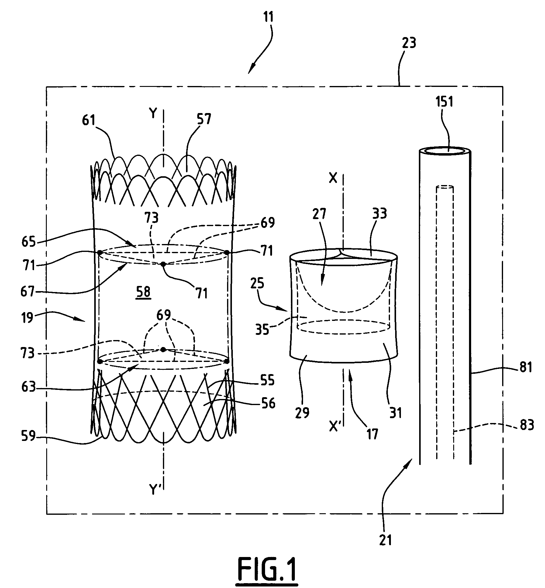
[0031]A first kit 11 according to the invention is shown in FIG. 1 to 3.

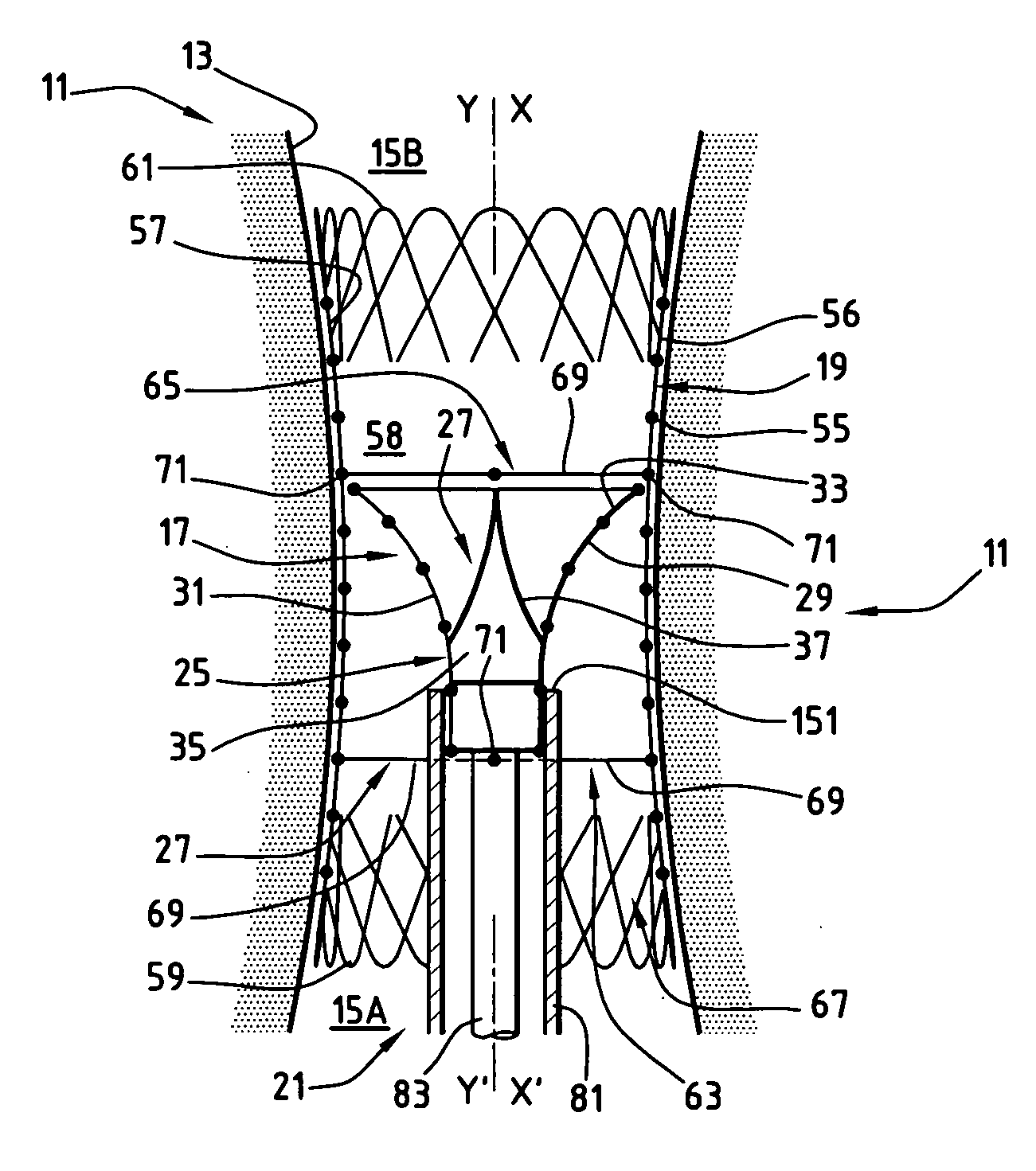
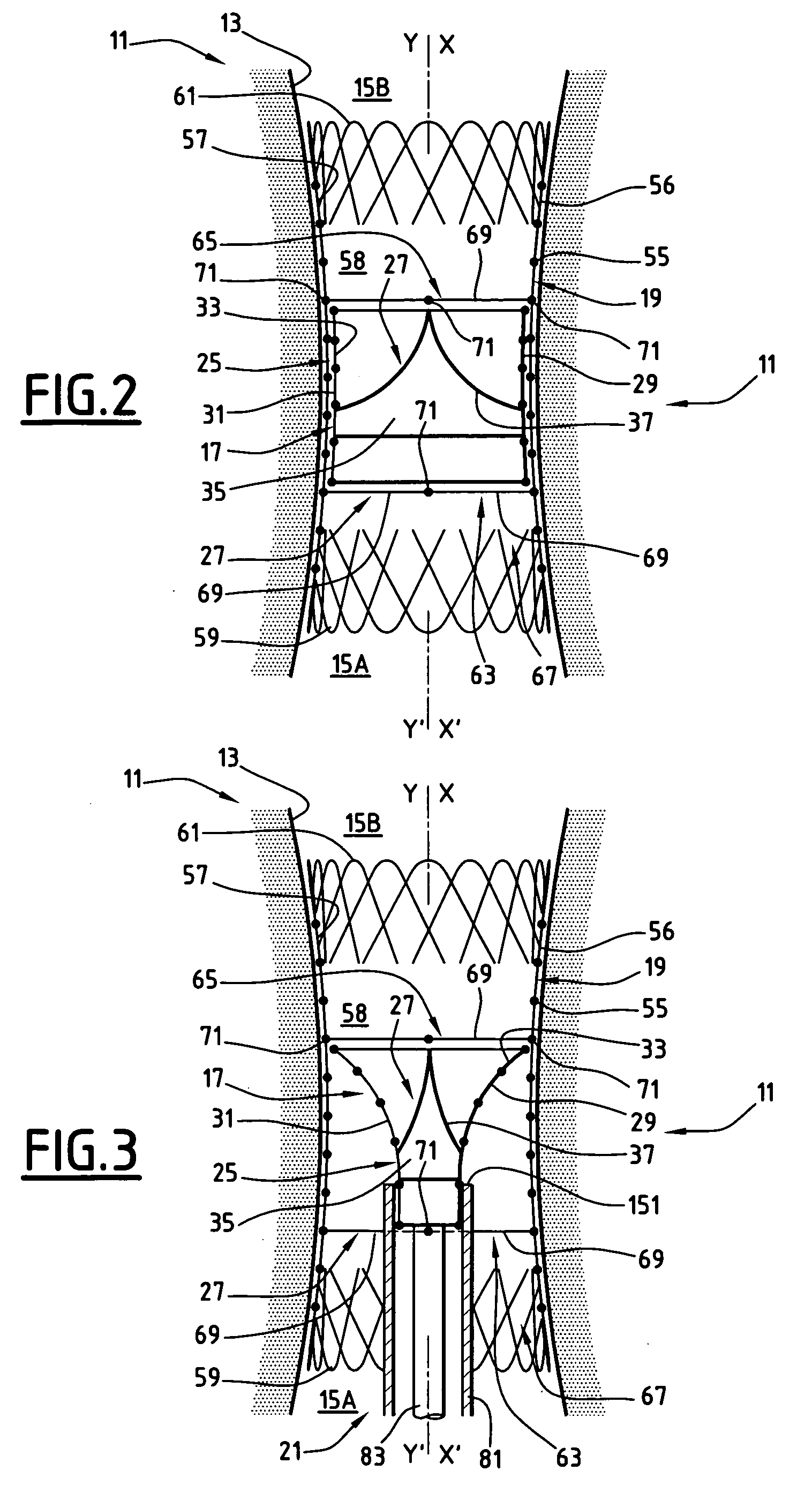
[0032]FIG. 1 shows the kit 11 prior to being implanted in a blood circulation conduit, whereas FIG. 2 shows the kit 11 implanted in a blood circulation conduit 13. The conduit 13 is, for example, a pulmonary artery connected at its proximal end 15A to the outlet of the right ventricle of the heart, in particular in a human being, and connected at its distal end 15B to the lung.

[0033]As shown in FIG. 1, the kit 11 comprises a prosthetic valve 17, an endoprosthesis 19 intended to receive the prosthetic valve 17 and a tool 21 for implanting the prosthetic valve 17 in the endoprosthesis 19.

[0034]The kit 11 is stored in packaging 23 for example.

[0035]As shown in FIG. 2, the prosthetic valve 17 comprises a supporting framework 25 and a deformable obturator 27 which is supported by the framework 25 and is integral therewith.

[0036]When the valve 17 is fitted in the endoprosthesis 19, said valve can move relative to the ...


PUM


Abstract

This kit (11) comprises a tubular endoprosthesis (19) having an inner surface (57) which delimits a channel (58) with a longitudinal axis (Y-Y′). It comprises a prosthetic valve (17) to be implanted in the channel (58). The valve (17) comprises a supporting framework (25) having an outer surface (31) to be applied against the inner surface (57), and a flexible obturator (27) which is connected to the framework (25).
The endoprosthesis (19) comprises a stop (63, 65) for locking the supporting framework (25) in order to block the axial displacement of the outer surface (31) along the inner surface (57) in at least a first direction. The stop (63, 65) comprises at least one flexible connection (69) extending transversely in the channel (58) between two connection points (71), which are located on the inner surface (57) and are angularly spaced about the axis (Y-Y′).

Description

TECHNICAL FIELD[0001]The present invention relates to a kit to be implanted in a blood circulation conduit, of the type comprising:[0002]a tubular endoprosthesis having an inner surface which delimits a channel with a longitudinal axis; and[0003]a prosthetic valve which can be moved relative to the tubular endoprosthesis in order to be implanted in the channel, the prosthetic valve comprising:[0004]a supporting framework having an outer surface to be applied against the inner surface of the endoprosthesis, the framework being radially deformable from a folded fitting position to a deployed implantation position;[0005]a flexible obturator which is connected to the framework, and is deformable between a closure position in which it extends transversely, and a release position in which it is contracted transversely due to the flow circulating in the channel;the endoprosthesis comprising at least one stop for locking the prosthetic valve in the channel in order to block axial displaceme...

Claims


Application Information

Patent Timeline
IPC IPC(8): A61F2/06A61F2/95
CPCA61F2/2418A61F2/2436A61F2002/9534A61F2250/006
Inventor STYRC, MYKOLAJ
Owner WL GORE & ASSOC INC
Why Eureka
Try Eureka