Check patentability & draft patents in minutes with Patsnap Eureka AI!

Optical Disk Apparatus

Inactive Publication Date: 2008-12-25
HITACHI CONSUMER ELECTRONICS CORP +1
View PDF8 Cites 1 Cited by
  • Summary
  • Abstract
  • Description
  • Claims
  • Application Information

AI Technical Summary

Benefits of technology

[0012]According to the present invention, looseness vibrations resulting from a gap between a sub-guide shaft and a bearing can be reduced.

Problems solved by technology

If looseness vibrations arise, a reading or recording error of information occurs.
The technology described in Japanese Patent Application Laid-Open No. 2002-92898 adjusts the position of a guide shaft relative to a chassis and cannot reduce looseness vibrations resulting from a gap between the guide shaft and the bearing.

Method used


Image

  • Optical Disk Apparatus
  • Optical Disk Apparatus
  • Optical Disk Apparatus

Examples


Embodiment Construction

[0034]A preferred embodiment to carry out an optical disc apparatus of the present invention will be described in detail below with reference to attached drawings. FIG. 1 to FIG. 5 are diagrams exemplifying the embodiment of the present invention and, in these figures, components to which the same reference numeral is attached represent the same component having a similar basic configuration and operation.

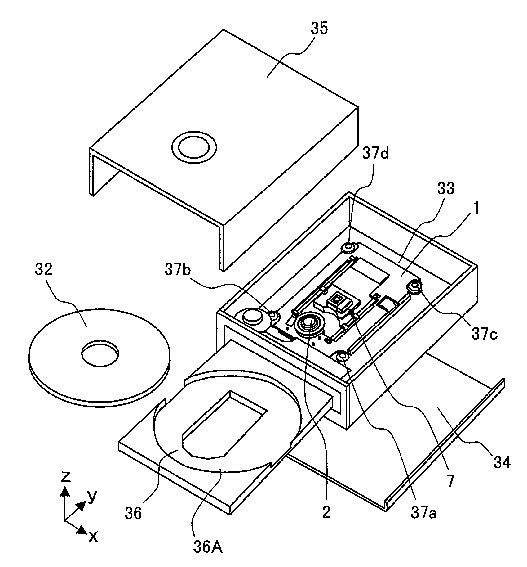
[0035]The configuration of an optical disc apparatus according to the present invention will be described with reference to FIG. 1. The optical disc apparatus in the present example records information on a recording surface of a disc 32 such as a compact disc (CD), digital versatile disc, (DVD), and blu-ray disc (BD) having dimensions of 120 mm in diameter and 1.2 mm in thickness and replays information from the recording surface.

[0036]The optical disc apparatus has a cabinet. The cabinet has a bottom cover 34 and a top cover 35 manufactured by pressing a metal plate such as a rol...


PUM


Abstract

An optical disc apparatus capable of reducing looseness vibrations resulting from a gap between a sub-guide shaft and a bearing is provided. According to an optical disc apparatus in the present invention, both ends of the sub-guide shaft are supported by being sandwiched between a pair of support parts formed in a chassis and a pair of pressing members mounted on the chassis. The support part is formed by bending a protruding portion both protruding in an inward direction of a hole from an edge of the hole of the chassis and extending along the direction perpendicular to the sub-guide shaft.

Description

BACKGROUND OF THE INVENTION[0001]1. Field of the Invention[0002]The present invention relates to an optical disc apparatus for driving an optical disc such as a compact disc (CD), digital versatile disc (DVD), and blu-ray disc (BD).[0003]2. Description of the Related Art[0004]An optical disc apparatus has an optical pickup for recording information on an optical disc or replaying information from the optical disc. The optical pickup is slidably maintained on both a main guide shaft and a sub-guide shaft mounted on a chassis, via a bearing. Therefore, the optical pickup is movable in a disc radius direction relative to the chassis.[0005]A support structure of the guide shaft of an optical disc apparatus commonly has a vibration isolation means. There are some cases in which the guide shaft or a support part of the guide shaft is formed of resin as such a vibration isolation means.[0006]Japanese Patent Application Laid-Open No. 2002-92898 discloses a technology to fix a guide shaft by...

Claims


Application Information

Patent Timeline
IPC IPC(8): G11B7/08
CPCG11B7/08582G11B19/2018G11B21/083
Inventor KATOU, SEIICHIYAMAUCHI, YOSHIAKINISHIDA, IKUONARUI, YOUICHI
Owner HITACHI CONSUMER ELECTRONICS CORP
Features
  • R&D
  • Intellectual Property
  • Life Sciences
  • Materials
  • Tech Scout
  • Unparalleled Data Quality
  • Higher Quality Content
  • 60% Fewer Hallucinations
Learn More