Drive Device

a technology of a drive device and a wing, which is applied in the direction of wing operation mechanisms, door/window fittings, constructions, etc., can solve the problem of not being able to twist to ensure satisfactory operation, and achieve the effect of saving considerable space, simple design, and reliable operation

Active Publication Date: 2009-01-01
STABILUS
View PDF11 Cites 13 Cited by
  • Summary
  • Abstract
  • Description
  • Claims
  • Application Information

AI Technical Summary

Benefits of technology

[0006]It is an object of the invention to create a drive device of the type described above which overcomes the previously cited disadvantages. This and other objects and advantages are achieved by the drive device in accordance with invention by providing a brake device which comprises a centrifugal force brake that is configured as a magnetic centrifugal force brake such that an especially simple design becomes possible. In an embodiment, the brake device comprises a first brake element and at least one second brake element. Here, the first brake element is supported on the rotary drive to guarantee especially reliable operation. The first brake element comprises a bore with a step, where the step provides a support surface for a magnet, which provides a considerable space savings.

Problems solved by technology

Here, the guide device is mounted on the drive shaft of the rotary drive such that it cannot twist to ensure satisfactory operation.

Method used


Image

  • Drive Device
  • Drive Device
  • Drive Device

Examples


Embodiment Construction

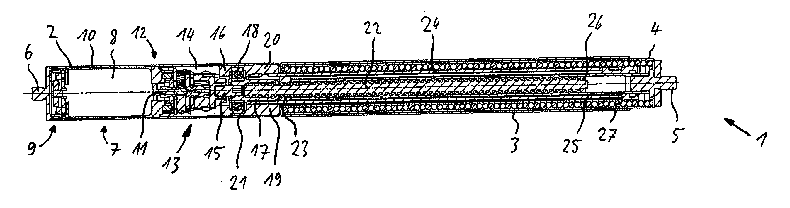
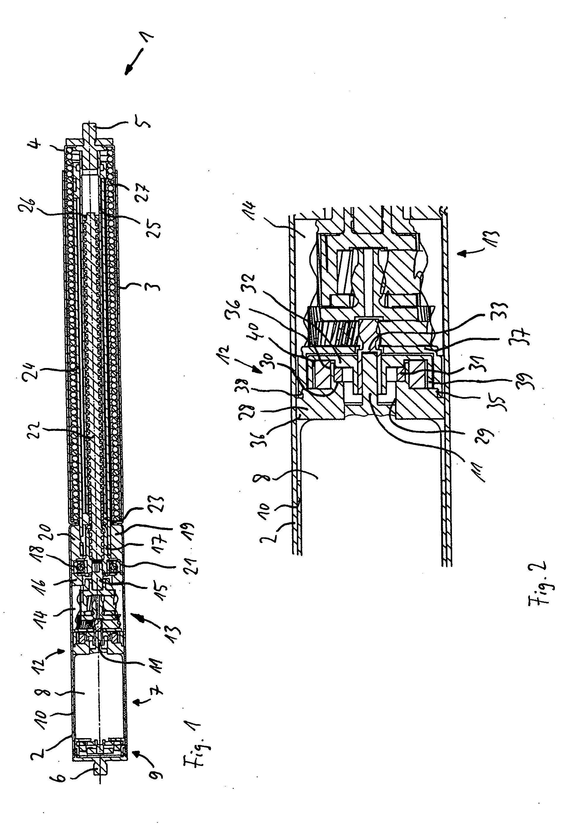
[0016]The drive device 1 shown in FIG. 1 has a first housing part 2, a second housing part 3, and a third housing part 4, which is telescopically guided in the second housing part 3 with an axial freedom of movement. A first connecting device 5 is mounted on the end of the third housing part 4 opposite the first housing part 2, and a second connecting device 6 is mounted on the end of the housing part 2 opposite the third housing part 4. The connecting devices 5 and 6 close off the ends of their respective housing parts 2 and 3. The connecting devices 5 and 6 have threads (not shown), so that they can be screwed onto connecting elements (not shown) in the form of ball sockets. The person of ordinary skill in the art, however, will appreciate that connecting techniques can also be used to connect the connecting devices 5 and 6 to the connecting elements, such as welding or creasing. As a result, the drive device can be attached in an articulated manner to a stationary body component ...


PUM


Abstract

A drive device for a hatch of a vehicle, wherein the device includes a first housing part which can be connected to a stationary component or to a movable component, a second housing part, a third housing part which is telescopically guided in the second housing part with an axial freedom of movement and which can be connected to the other of the movable component or the stationary component. A spindle drive comprising a threaded spindle and a spindle nut is mounted on the threaded spindle, by which the third housing part can be driven by a rotary drive and, thus, moved axially with respect to the second housing part. The drive device also includes a brake device, where the brake device comprises a centrifugal force brake.

Description

BACKGROUND OF THE INVENTION[0001]1. Field of the Invention[0002]The invention is directed to a drive device for a hatch of a motor vehicle having a first housing part, which can be connected to a stationary component or to a movable component, a second housing part, and a third housing part, which is guided in the second housing part with freedom of telescopic movement, and which can be connected to a movable component or to a stationary component. The drive device also includes a spindle drive comprising a threaded spindle and a spindle nut mounted on the threaded spindle, by which the third housing part can be driven by a rotary drive and thus moved axially with respect to the second housing part, and a brake device.[0003]2. Description of the Related Art[0004]In conventional drive devices, it should be possible not only to allow the drive device to move the hatch of a vehicle automatically but also to move the hatch manually. Here, the manual forces required for moving the hatch ...

Claims


Application Information

Patent Timeline
Patent Type & Authority Applications(United States)
IPC IPC(8): E05F15/00
CPCE05Y2201/21E05Y2201/242E05F15/622E05Y2201/266E05Y2900/546E05Y2201/26
Inventor FAHL, DANIEL
Owner STABILUS
Why Eureka
Try Eureka