Roller assembly for a frameless sliding glass door

a roll assembly technology, applied in door/window fittings, multi-purpose tools, construction, etc., can solve the problems of the bottom of the frameless sliding glass door not being able to make contact with the ground, and the person cannot adjust the position

Inactive Publication Date: 2009-01-01
DOOR & WINDOW HARDWARE
View PDF17 Cites 10 Cited by
  • Summary
  • Abstract
  • Description
  • Claims
  • Application Information

AI Technical Summary

Benefits of technology

[0010]The main objective of the present invention is to provide a roller assembly that can allows a frameless sliding glass door to be easily set parallel to the ground.

Problems solved by technology

However, the mounting holes in the brackets are circular holes and a person cannot adjust the position between the conventional roller assemblies and the frameless sliding glass door.
When the track is mounted at an undesired angle on a wall, such as slanting or at an angle from the horizon, a bottom of the frameless sliding glass door will not be parallel to the ground and this may cause the bottom of the frameless sliding glass door to make contact with the ground.
Furthermore, the mounting holes of the brackets of the conventional roller assemblies may not parallel to each other, and this also influence the accuracy of mounting the frameless sliding glass door on the track.

Method used


Image

  • Roller assembly for a frameless sliding glass door
  • Roller assembly for a frameless sliding glass door
  • Roller assembly for a frameless sliding glass door

Examples


Embodiment Construction

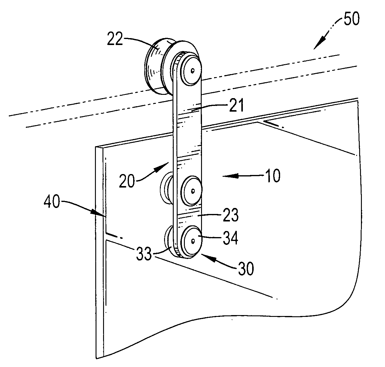
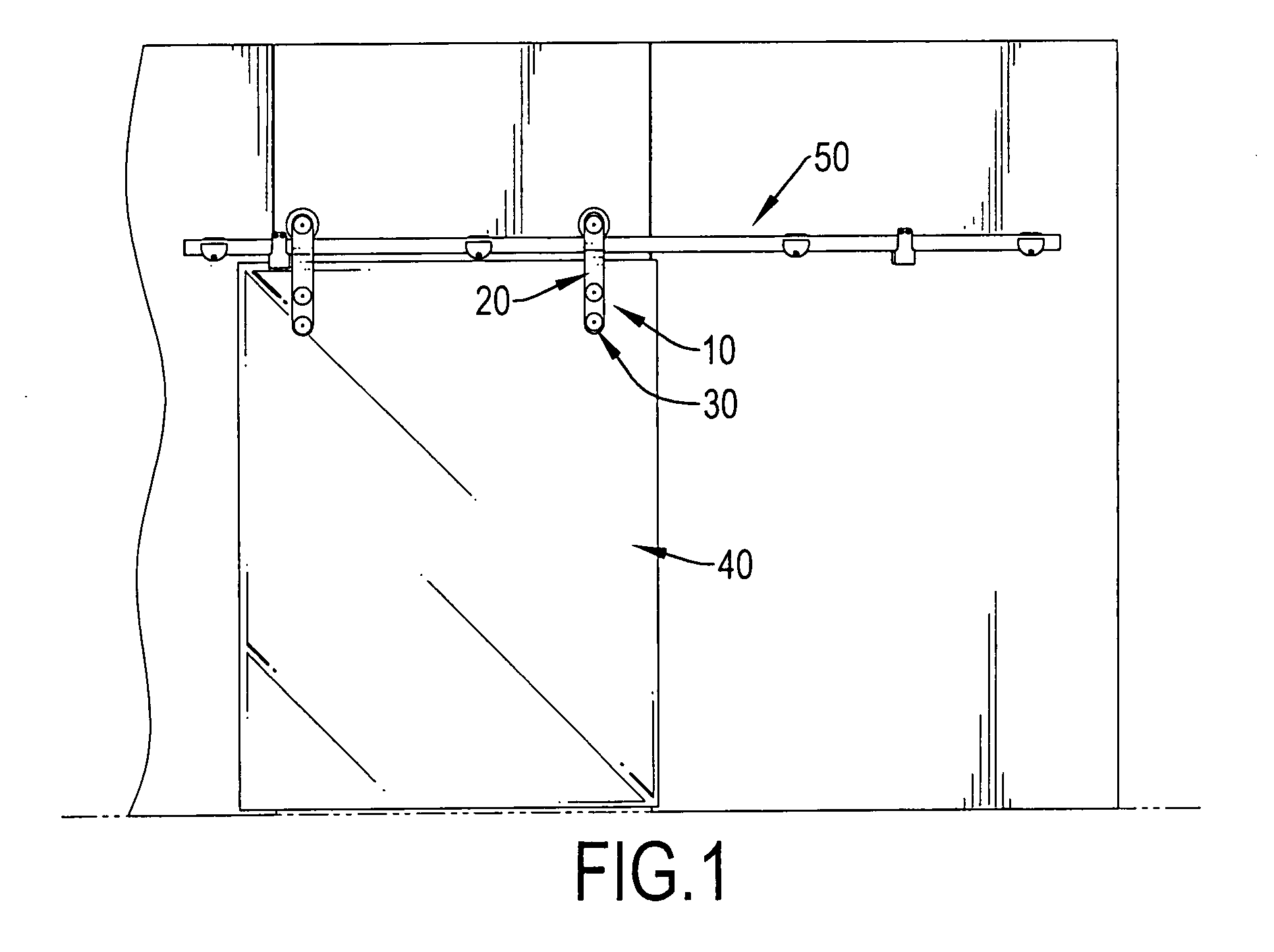
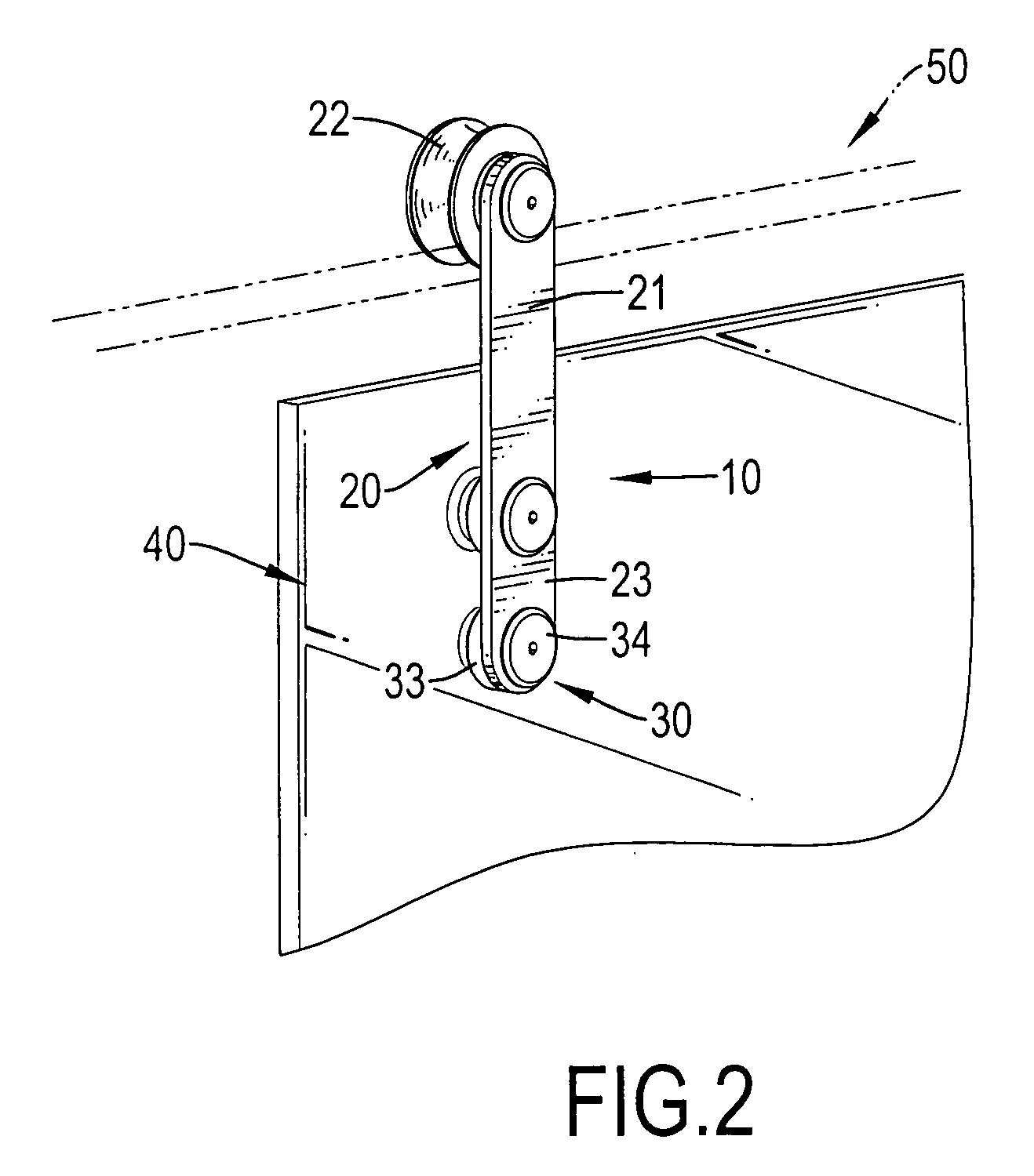
[0017]With reference to FIGS. 1 to 3, a roller assembly (10) in accordance with the present invention is connected to a frameless sliding glass door (40), to a track (50) and comprises a bracket (20), a roller (22) and at least one fastening device (30).

[0018]The frameless sliding glass door (40) has at least one through hole (41) and a bottom. The track (50) is mounted on a wall.

[0019]The bracket (20) is attached to the frameless sliding glass door (40) and the track (50) and has a rear surface, an upper end (21), a lower end (23), a lower edge, at least one elongated hole (24), an adjustment hole (25) and a set screw (26). At least one elongated hole (24) is formed through the bracket (20) in the lower edge and corresponds to the at least one through hole (41) in the frameless sliding glass door (40). The adjustment hole (25) is formed through the lower edge of the bracket (20) and communicates with the elongated hole (24) in the lower end of the bracket (20). The set screw (26) i...


PUM


Abstract

A roller assembly for a frameless sliding glass door has a bracket, a roller and at least one fastening device. The bracket is attached to the frameless sliding glass door and a track and has at least one elongated hole, an adjustment hole and a set screw. The at least one elongated hole is formed through the bracket near the lower end. The adjustment hole is formed through the lower edge of the bracket and communicates with the elongated hole in the lower end of the bracket. The set screw is threaded and corresponds with the adjustment hole. The roller is rotatable connected to the rear surface of the bracket in the upper end and mounted on the track. The fastening device is connected to the bracket and the frameless sliding glass door through the elongated hole and the corresponding through hole.

Description

BACKGROUND OF THE INVENTION[0001]1. Field of the Invention[0002]The present invention relates to a roller assembly, and more particularly relates to a roller assembly that allows a frameless sliding glass door to be set to parallel to the ground easily and adjust a crack between the frameless sliding glass door and the ground.[0003]2. Description of Related Art[0004]A frameless sliding glass door has a top, two conventional roller assemblies and a track. The conventional roller assemblies are connected to a top of the frameless sliding glass door with multiple through holes to slidably mount the frameless sliding glass door on the track. Each conventional roller assembly has a bracket, a roller and multiple fastening devices.[0005]The bracket has a rear surface, an upper end, a lower end and multiple mounting holes. The mounting holes are formed through the bracket near the lower end and correspond to the through holes in the frameless sliding glass door.[0006]The roller is rotatabl...

Claims


Application Information

Patent Timeline
Patent Type & Authority Applications(United States)
IPC IPC(8): E05D15/06E05D13/00
CPCE05D5/0246E05D15/0634E05Y2201/684E05Y2800/16Y10T16/364E05Y2800/672E05Y2900/132Y10T16/3834Y10T16/3825E05Y2800/28E05Y2900/00
Inventor CHANG, JAMESHSIEH, CHIH-LUN
Owner DOOR & WINDOW HARDWARE
Why Eureka
Try Eureka