Disc refiner with plates having logarithmic spiral bars

a disc refiner and spiral bar technology, applied in the field of refining discs and plate segments, can solve the problem of inhomogeneous distribution of material in the gap as a function of radial and angular position, and is unavoidable by conventional bar designs

Inactive Publication Date: 2009-01-01
DURAMETAL CORP
View PDF8 Cites 13 Cited by
  • Summary
  • Abstract
  • Description
  • Claims
  • Application Information

AI Technical Summary

Benefits of technology

[0007]Accordingly, the object of the present invention is to provide a refining element bar shape with the desired feature of constant bar and thus constant crossing angle to promote a more homogeneous refining action.
[0011]An additional feature of the logarithmic spiral is the variability of groove width, i.e., the distance between adjacent bars with respect to radial position. This makes the grooves open up in the direction of stock flow, which prevents plugging of the grooves with fibers and tramp material.

Problems solved by technology

Therefore an inhomogeneous distribution of material in the gap as a function of radial and angular position is unavoidable by conventional bar designs.

Method used


Image

  • Disc refiner with plates having logarithmic spiral bars
  • Disc refiner with plates having logarithmic spiral bars
  • Disc refiner with plates having logarithmic spiral bars

Examples


Embodiment Construction

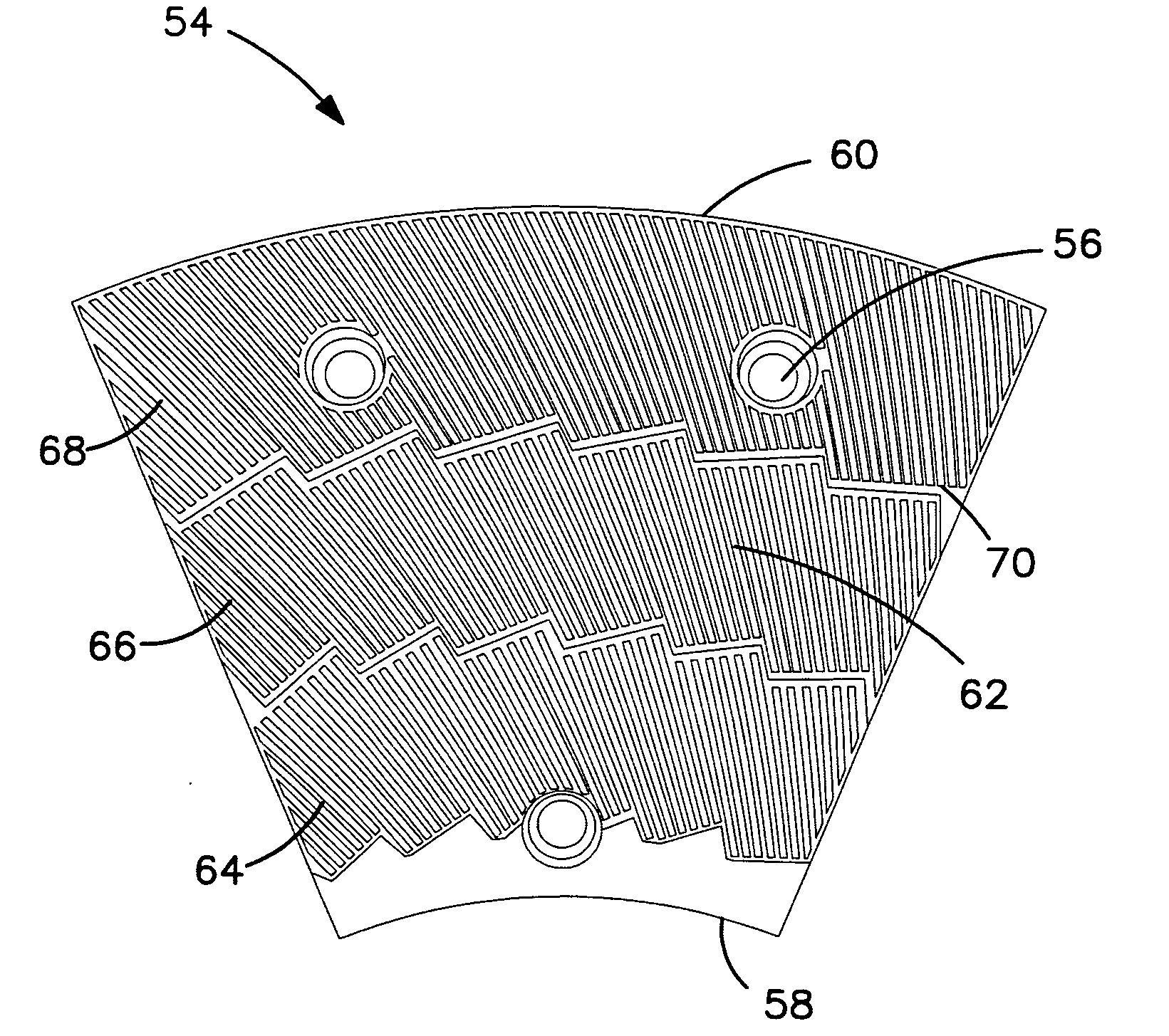
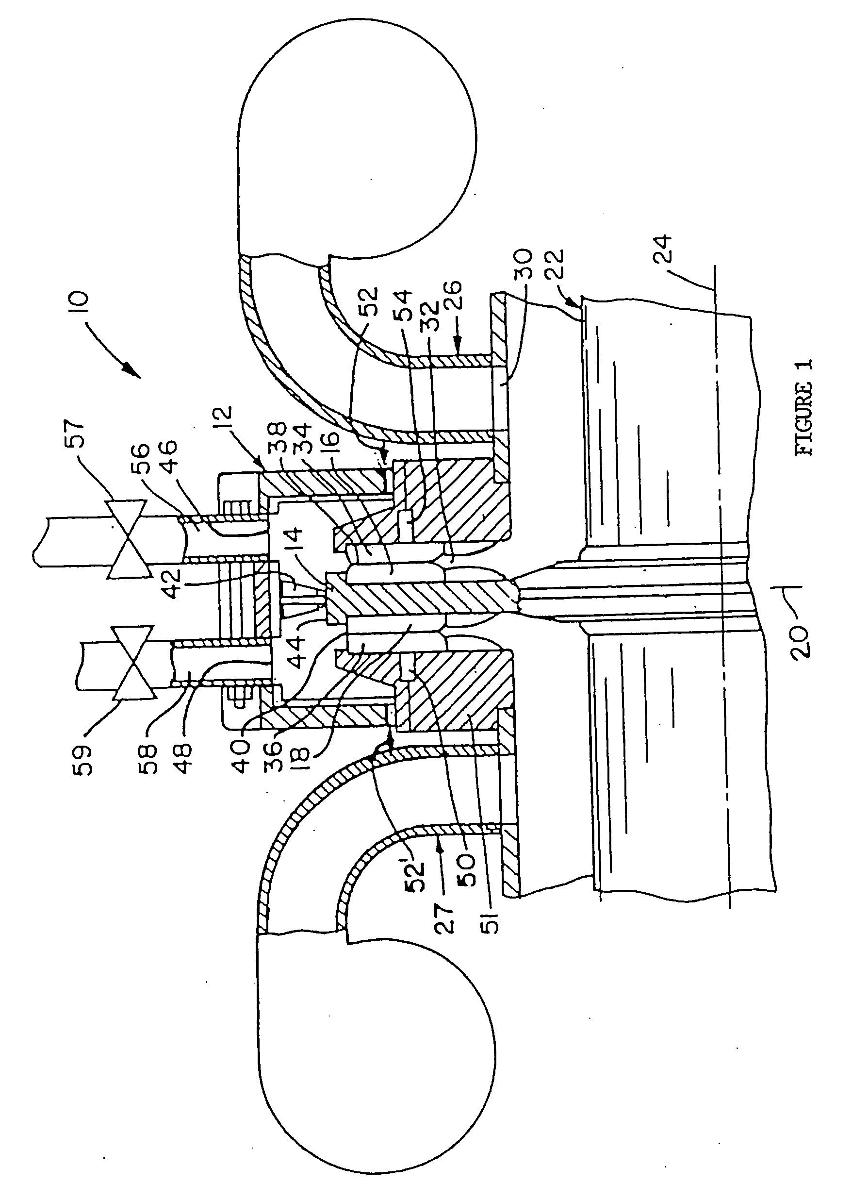
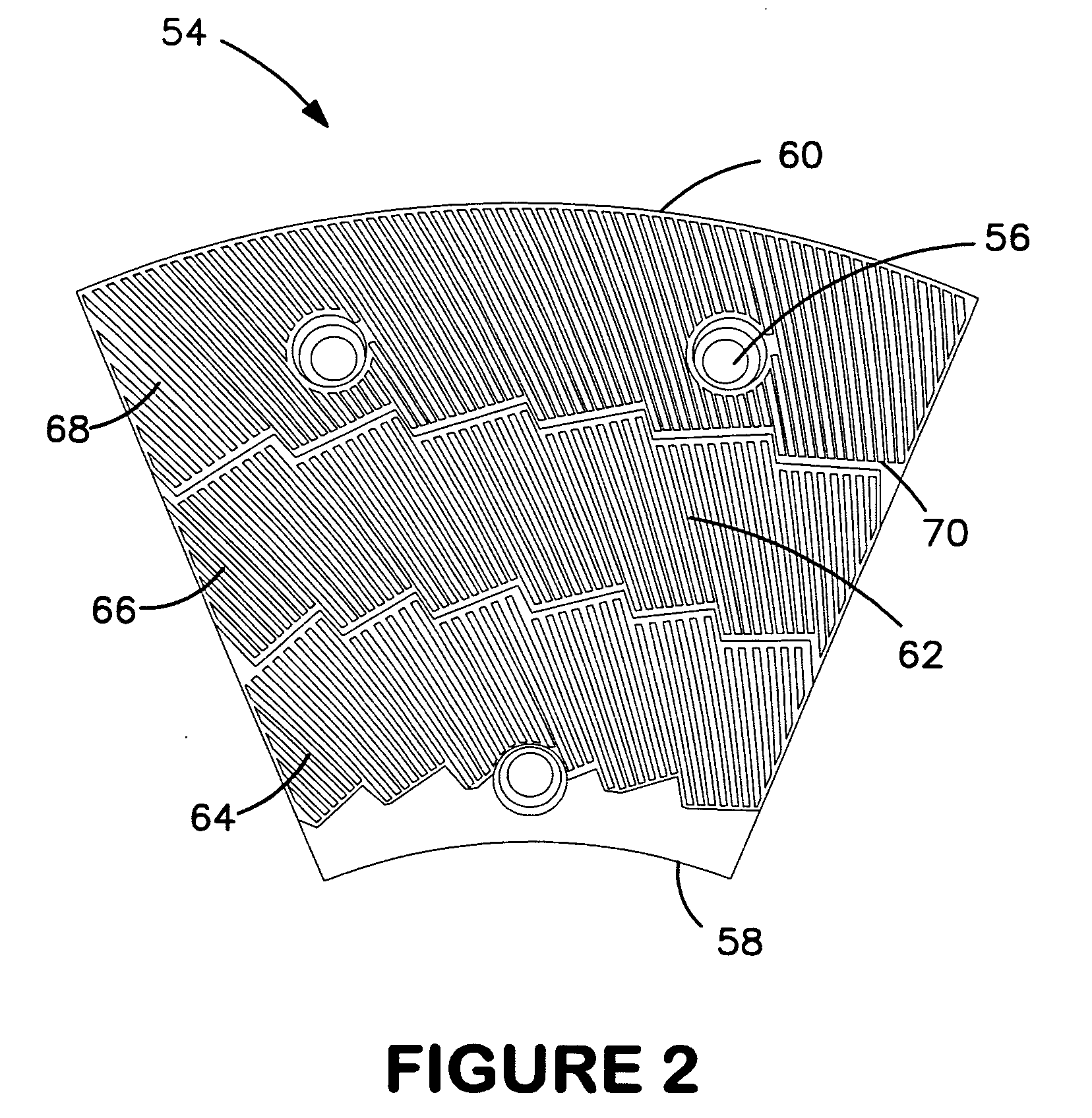
[0031]FIG. 1 is a schematic showing a refiner 10 with casing 12 in which opposed discs are supported, each of which carries an annular plate or circle consisting of a plurality of plate segments. The casing 12 has a substantially flat rotor 14 situated therein, the rotor carrying a first annular plate defining a first grinding face 16 and a second annular plate defining a second grinding face 18. The rotor 14 is substantially parallel to and symmetric on either side of, a vertical plane indicated at 20. A shaft 22 extends horizontally about a rotation axis 24 and is driven at one or both ends (not shown) in a conventional manner.

[0032]A feed conduit 26 delivers a pumped slurry of lignocellulosic feed material through inlet opening 30 on either side of the casing 12. At the rotor, the material is re-directed radially outward through the coarse breaker region 32 whereupon it moves along the first grinding face 16 and a third grinding face 34 juxtaposed to the first face so as to defin...


PUM

PropertyMeasurementUnit
crossing angleaaaaaaaaaa
angleaaaaaaaaaa
angleaaaaaaaaaa

Abstract

A special shape of bars on refining discs or plate segments of a rotating disc refiner is disclosed including a plurality of bars generally extending outwards towards the outer end of the disk across its surface, arranged in a single, two or more radial zones, the plurality of the bars within a zone being curved with the shape of a logarithmic spiral. Disc refiners including such refining discs are also disclosed.

Description

RELATED APPLICATIONS[0001]This is a divisional of U.S. application Ser. No. 10 / 476,779 filed Nov. 5, 2003, which was the national stage application based on International Application PCT / US03 / 12417 filed Apr. 22, 2003, which claims. priority under 35 U.S.C. Sec. 119(e) from U.S. Provisional Application No. 60 / 375,531 filed Apr. 25, 2002.BACKGROUND OF THE INVENTION[0002]The present invention relates to refining discs and plate segments for refining discs, and more particularly to the shape of the bars that define the refining elements of the discs or segments.[0003]Disc refiners for lignocellulosic material, ranging from saw dust to wood chips, are fitted with refining discs or segments. The material to be refined is treated in a gap defined between two refining discs rotating relative to each other. The material moves in the grooves formed by the bars located on the disc surfaces, both in a generally radial plane, providing a transport function, and out of plane, providing a mechani...

Claims


Application Information

Patent Timeline
Patent Type & Authority Applications(United States)
IPC IPC(8): B02C7/12B02C7/02D21D1/30
CPCB02C7/12D21D1/306D21D1/303
Inventor ANTENSTEINER, PETER
Owner DURAMETAL CORP
Why Eureka
Try Eureka