Aircraft engine balanced thrust vectoring system

a thrust vectoring system and aircraft engine technology, applied in the direction of aircraft, vertical landing/take-off aircraft, vehicles, etc., can solve the problems of insufficient stabilization of aircraft, relatively complex gimballed exhaust nozzle systems, etc., to achieve simple thrust vectoring, maximize the flow efficiency of exhaust, and stabilize the effect of hover stability

Inactive Publication Date: 2009-01-01
KIRSTEIN JOSHUA M
View PDF13 Cites 8 Cited by
  • Summary
  • Abstract
  • Description
  • Claims
  • Application Information

AI Technical Summary

Benefits of technology

[0007]A thrust vectoring system for an aircraft is disclosed herein, designed to provide even weight distribution, simple thrust vectoring, and hover stability. The system includes a thrust diverter that is longitudinally aligned with an output exhaust port on a jet engine. Located inside the thrust diverter is a splitter which evenly divides the exhaust from the jet engine into four separate, duct assemblies. The four duct assemblies are divided into two duct pairs: a front duct pair and a rear duct pair, the two ducts in each duct pair are transversely aligned and equally spaced apart from the diverter's transverse axis. Each duct extends upward in an equal distance above the thrust diverter's longitudinal axis and includes an upper curved nozzle that bends laterally and diagonally downward thereby delivering exhaust on opposite sides of the diverter's longitudinal and transverse axis. The size and shape of each duct in the duct pair are complimented with a mirror image of each other so that the amount of exhaust from each duct is equal. Each duct has only two bends which maximizes the exhaust's flow efficiency therein. The shape and diameter of each duct uniform their entire length which also maximizes exhaust flow.

Problems solved by technology

One drawback, which is addressed with the thrust vectoring system disclosed herein is that the gimballed exhaust nozzle systems currently used are relatively complex and do not adequately stabilize the aircraft when vertically lifting the aircraft or when performing hovering maneuvers.

Method used


Image

  • Aircraft engine balanced thrust vectoring system
  • Aircraft engine balanced thrust vectoring system
  • Aircraft engine balanced thrust vectoring system

Examples


Embodiment Construction

)

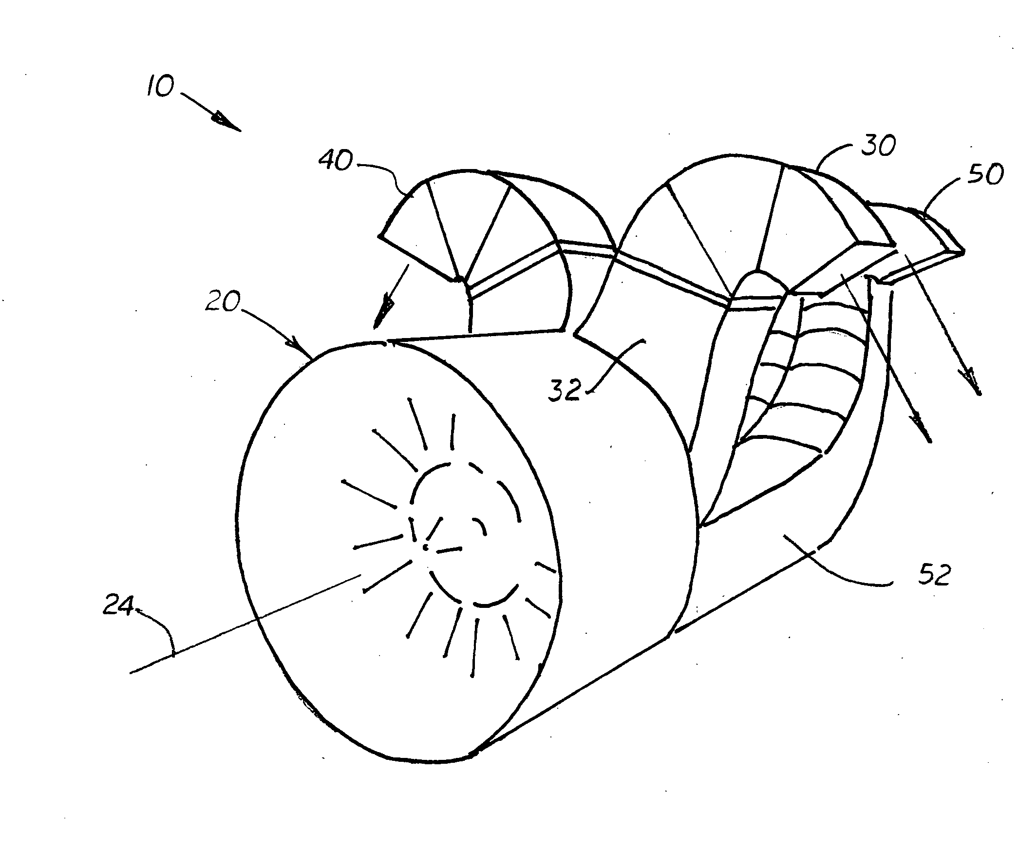
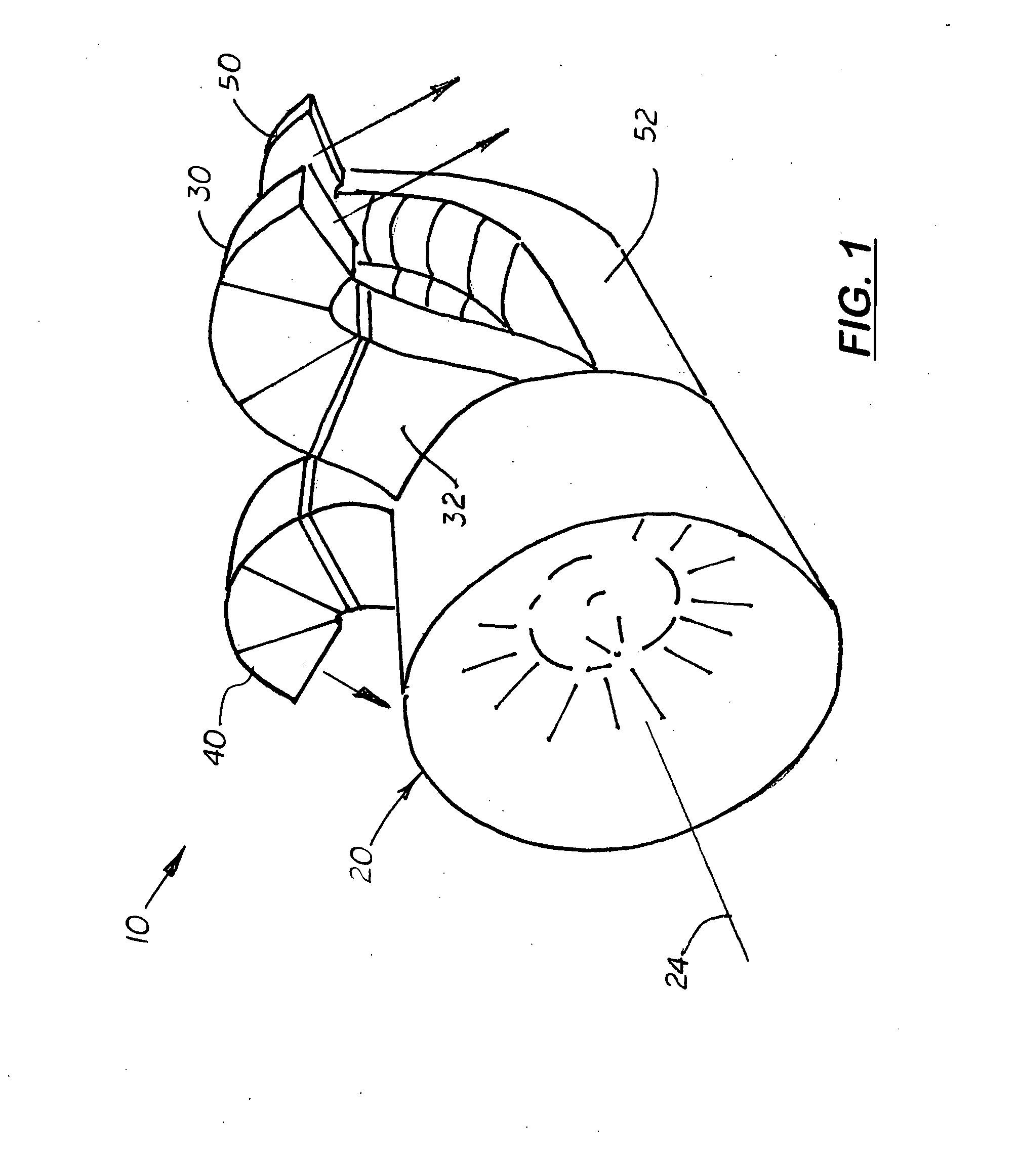
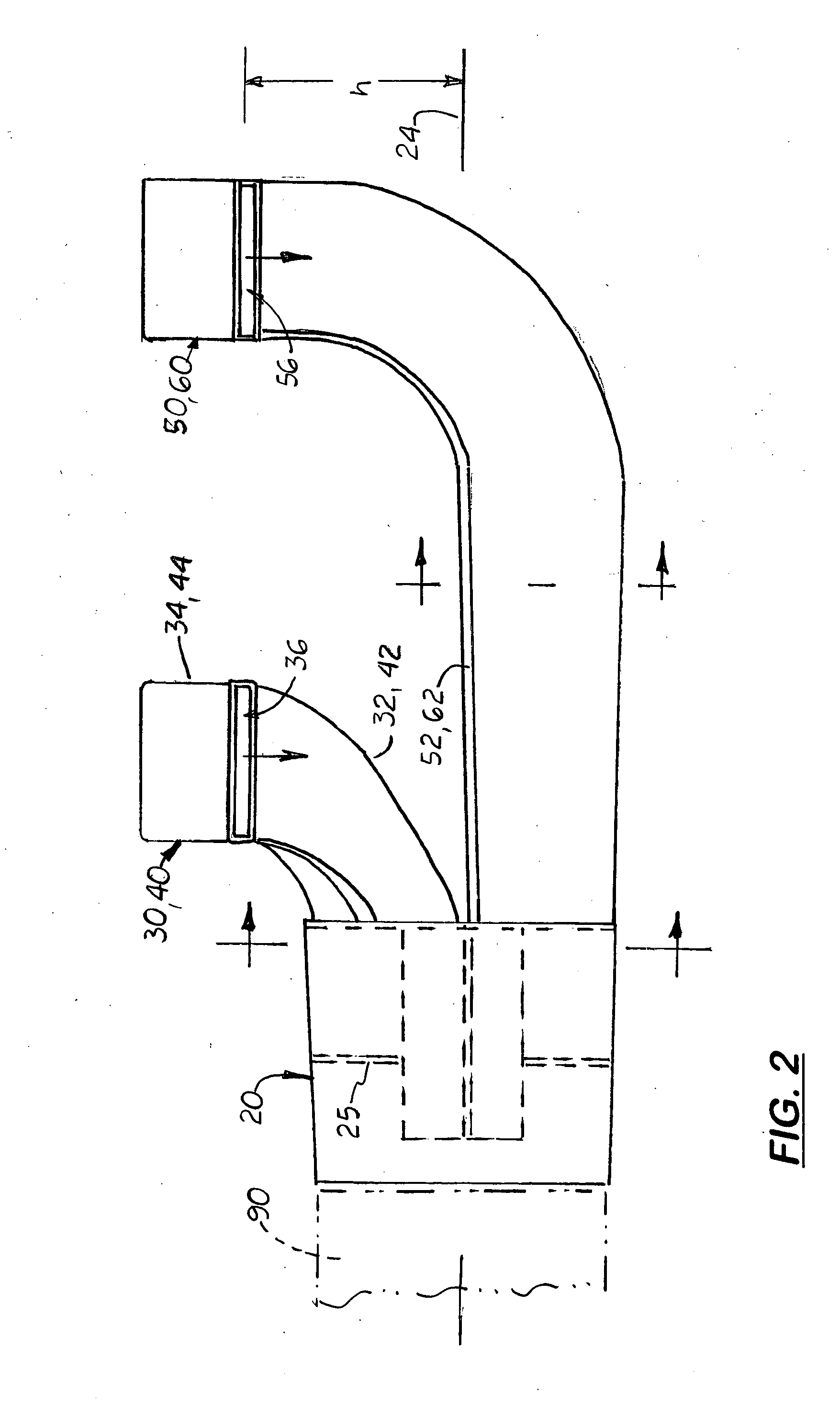
[0014]Referring to the FIGS. 1-6 there is shown a balanced thrust vectoring system 10 for an aircraft designed to provide even weight distribution, simple thrust vectoring, and hover stability. The system 10 includes a cylindrical thrust diverter 20 that is longitudinally aligned with an output exhaust port on a jet engine 90 (see FIG. 2). Located inside the thrust diverter 20 is a four way splitter 25 which evenly divides the flow of exhaust from the jet engine 90 into four separate volumes 26-29 (see FIG. 5). Attached and extending rearward from the diverter 20 and longitudinally aligned with each duct volume 26-29 is a fixed duct 30, 40, 50, and 60, respectively, which evenly distributes the exhaust from the diverter 20 to provide balanced vertical lift on the aircraft.

[0015]In the preferred embodiment, the four ducts 30, 40, 50, 60 are divided into two pairs: a front duct pair 65 and a rear duct pair 70. The two ducts 30, 40 and 50, 60 in each duct pair 65, 70, respectively, ar...


PUM


Abstract

A balanced thrust vectoring system for an aircraft designed to provide even weight distribution, simple thrust vectoring, and hover stability. The system includes a main diverter that connects to a jet output port. Located inside the diverter is a 4 way splitter that divides the diverter into four equal volumes. Attached to the diverter and adjacent to the two upper volumes are two front upward extending ducts. Attached to the diverter and adjacent to the two lower volumes are two rear upward extending ducts. Each duct includes an upper bend that and diagonally aligned nozzle opening. Each duct has only two bends which help vector the exhaust downward in an efficient manner. The diameter of each duct is consistent to allow their entire length to maximize air flow.

Description

[0001]This is a utility patent application which claims benefit of U.S. Provisional Application No. 60 / 925,970 filed on Apr. 23, 2007.BACKGROUND OF THE INVENTION[0002]1. Field of the Invention[0003]This invention relates to aircraft thrust diffusers, and more particularly to thrust diffusers that evenly distribute the flow of expelled air on opposite sides of the outlet's axis.[0004]2. Description of the Related Art[0005]Thrust vectoring is used in VTOL and STOL aircraft to redirect thrust from a main engine that is parallel to the aircraft's longitudinal axis to a downward direction to vertically lift the aircraft. In order to lift the aircraft vertically, the direction of thrust must be maintained through the aircraft's center of gravity. This is normally performed by using gimballed exhaust nozzles that rotate from a horizontal position to produce forward thrust and a vertical position to produce vertical lift. The gimballed exhaust nozzles must also swivel from side-to-side so t...

Claims


Application Information

Patent Timeline
Patent Type & Authority Applications(United States)
IPC IPC(8): B64C29/00
CPCB64C29/0066
Inventor KIRSTEIN, JOSHUA M.
Owner KIRSTEIN JOSHUA M
Why Eureka
Try Eureka