Integrated Lumbar and Active Head Rest System

a headrest system and integrated technology, applied in the direction of pedestrian/occupant safety arrangements, vehicle components, vehicle arrangements, etc., can solve the problems of limiting the flexibility and range of travel of any such lumbar support system, redundancy of traditionally discrete units, and the effect of increasing the range of travel of the lumbar suppor

Inactive Publication Date: 2009-01-01
SCHUKRA OF NORTH AMERICA
View PDF3 Cites 63 Cited by
  • Summary
  • Abstract
  • Description
  • Claims
  • Application Information

AI Technical Summary

Benefits of technology

[0012]In the present invention, the lumbar support is in a cooperative relationship with a crossbar in the energy transfer mechanism. In particular, to activate the energy transfer mechanism, the lumbar support moves the crossbar which extends inwardly from a pair of side bars. The lumbar support of the present invention is also different from

Problems solved by technology

In some rear impact situations, the upper torso, neck, and head of the passenger can then be forced back into the seatback, resulting in a whiplash effect.
Additionally, these combinations are usually limited to a particular type of lumbar device that must be designed specifically according to the active headrest system which can limit the flexibility and range of travel of any suc

Method used


Image

  • Integrated Lumbar and Active Head Rest System
  • Integrated Lumbar and Active Head Rest System
  • Integrated Lumbar and Active Head Rest System

Examples


Embodiment Construction

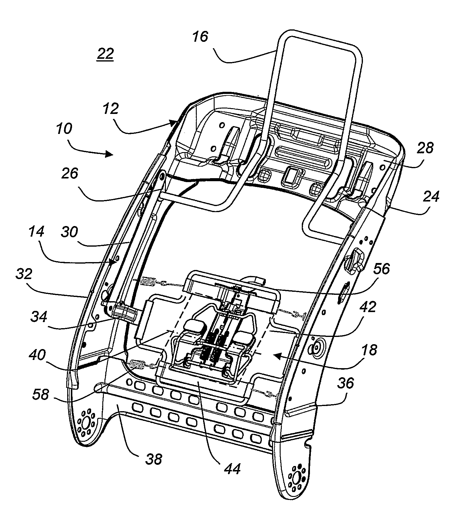
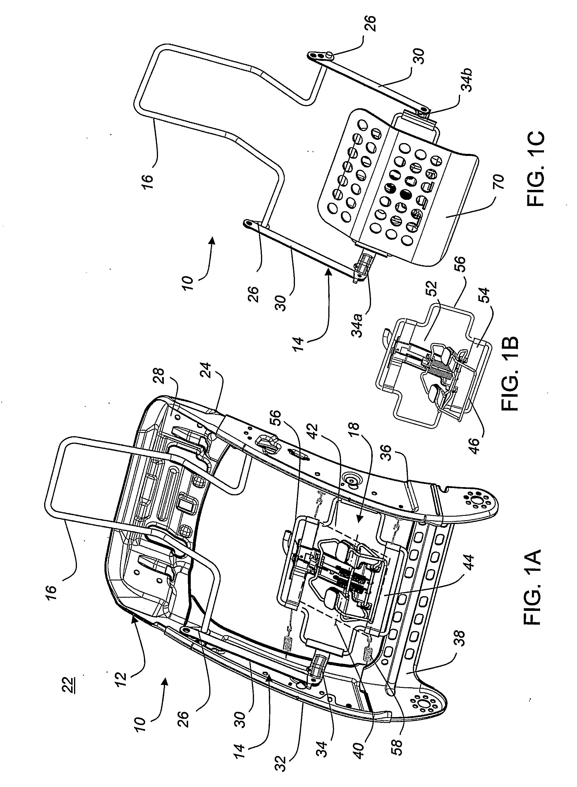
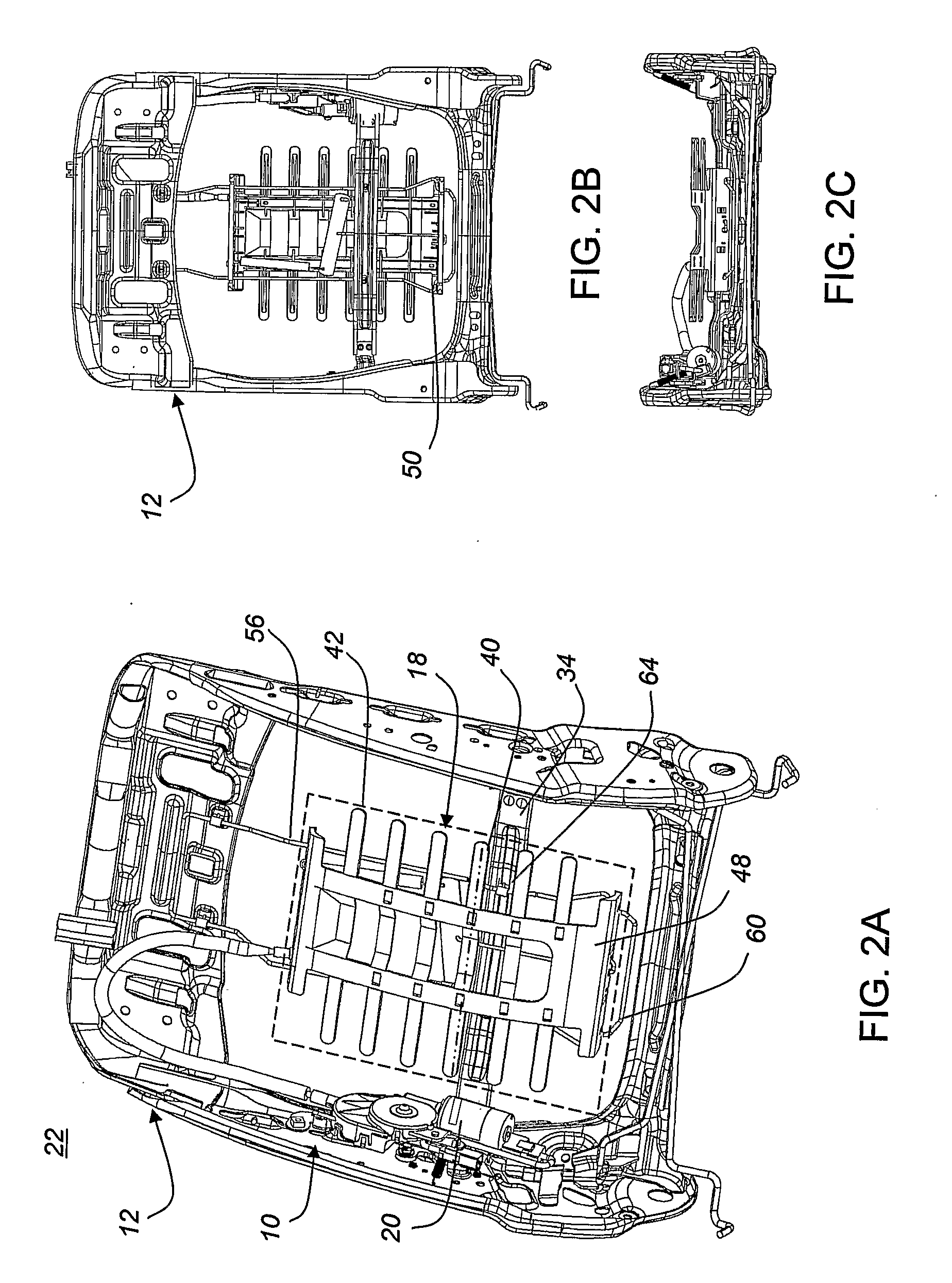
[0021]Referring to the accompanying drawings in which like reference numbers indicate like elements, each of the embodiments described below with reference to the corresponding illustrations is for an active headrest system 10 that can be adapted to fit into the seat frame 12 of any vehicle. In FIGS. 1 and 2, the active headrest system 10 is shown to include an energy transfer mechanism 14 that connects the headrest 16 to the lumbar support 18. The lumbar support 18 is operated by an actuator 20. Generally, the active headrest system 10 combined with the seat frame 12 and the actuator 20 is an integrated active headrest / lumbar seating system 22.

[0022]At the upper end 24 of the seat frame 12, a pair of linkages 26 connects the energy transfer mechanism 14 to the headrest 16 which is supported at the upper end 24 by a top beam 28. A pair of side bars 30 extend from the corresponding pair of linkages 26 along the side rails 32 of the seat frame 12 to a crossbar 34. The crossbar 34 conn...


PUM


Abstract

An integrated active headrest/lumbar seating system 22 includes an active headrest system 10 supported within a seat frame 12 of a vehicle. The active headrest system 10 includes an energy transfer mechanism 14 that connects the headrest 16 to the lumbar support 18. The lumbar support 18 is operated by an actuator 20. The energy transfer mechanism 14 includes a pair of linkages 26, a pair of side bars 30 and a cross bar 34. The linkages 25 connect to the headrest 16 and the pair of side bars 30 extend from the pair of linkages 26 along the side rails 32 of the seat frame 12 to the crossbar 34. The crossbar 34 connects the pair of side bars 30 and is situated at the middle section 40 of the lumbar support 18. The lumbar support 18 can fit between the side bars 30.

Description

CROSS-REFERENCE TO RELATED APPLICATIONS[0001]This application claims the benefit of U.S. Provisional Application No. 60 / 567,238 filed on Apr. 30, 2004 which is incorporated herein by reference.STATEMENT REGARDING FEDERALLY SPONSORED RESEARCH OR DEVELOPMENT[0002]Not Applicable.APPENDIX[0003]Not Applicable.BACKGROUND OF THE INVENTION[0004]1. Field of the Invention[0005]This invention relates generally to active headrest systems and, more particularly, to active headrest systems combined with lumbar support devices.[0006]2. Related Art[0007]Active headrest systems (AHRS) with energy transfer mechanisms are generally known in seat support systems to improve the safety of vehicle passengers in the event of a collision, and improvements have been made to reduce injuries to the neck region of the passenger. In the event of a rearward impact, the occupant of a seat in the vehicle is forced against the seat. Generally, the pelvis and lumbar regions of the occupant initially exert more force ...

Claims


Application Information

Patent Timeline
IPC IPC(8): B60N2/42B60N2/427B60N2/48B60N2/66
CPCB60N2/42727B60N2/66B60N2/4885B60N2/42781B60N2/6671B60N2/888A47C7/38B60N2/42
Inventor SWAN, DAVIDMCMILLEN, ROBERT J.COLJA, RENATOCERTOSSI, STEPHENSAMI, ASADKUKUROZOVIC, GEORGERENCZ, BOGDAN
Owner SCHUKRA OF NORTH AMERICA
Why Eureka
Try Eureka