Image display device and manufacturing method thereof

a technology of image display device and manufacturing method, which is applied in the manufacture of discharge tube luminescnet screen, electric discharge tube/lamp, electrode system, etc., can solve problems such as reliability problems, voltage drop caused by wiring resistance of second electrode, and hinder the uniform operation of electron sources, so as to ensure the reliability of electron radiation characteristics, prevent deterioration in vacuum, and long useful life

Inactive Publication Date: 2009-01-01
HITACHI LTD
View PDF4 Cites 2 Cited by
  • Summary
  • Abstract
  • Description
  • Claims
  • Application Information

AI Technical Summary

Benefits of technology

[0038]By using a construction in which the insulating film is covered and hidden by the second electrodes, it is possible to prevent contact between the insulating film and the sealing member, to prevent a deterioration in vacuum caused by foaming, to ensure the reliability of electron radiation characteristics, and to achieve a long useful life. Furthermore, in cases where the second electrodes are formed with a laminated construction of a lower-layer film and upper-layer film, it is possible to reduce the resistance of the second electrodes, and to improve the reliability of electrical feeding and continuity. Furthermore, in cases where insulating films are left on the undersides of the second electrodes in the sealed areas, it is possible to utilize these insulating films as protective films for other electrodes in subsequent processes, and a drop in the working efficiency can be prevented.

Problems solved by technology

Since this second electrode current causes a voltage drop along the second electrodes by the wiring resistance, the uniform operation of the electron sources is hindered.
In particular, the voltage drop caused by the wiring resistance of the second electrodes is a major problem in producing a large display device.
Then problems in reliability occur, e.g., the quality of the electron acceleration layer drops, the second electrodes and the like tend to be cut, and so forth.
However, Cu readily oxidizes; for example, in cases where Cu is used in an FPD panel, Cu tends to readily oxidize in the high-temperature sealing process.
However, when Cu is sandwiched above and below by metals with a high oxidation resistance, although most of the Cu escapes oxidation, the oxidation of the side surfaces of the wiring cannot be prevented.
However, as a result of the oxidation of the wiring side surfaces, undercut portions formed by the Cu and the under-layer film may undergo deformation, and the pixel separation characteristics may deteriorate.

Method used


Image

  • Image display device and manufacturing method thereof
  • Image display device and manufacturing method thereof
  • Image display device and manufacturing method thereof

Examples


Embodiment Construction

[0082]An embodiment of the present invention will be described in detail hereinbelow with reference to the drawings.

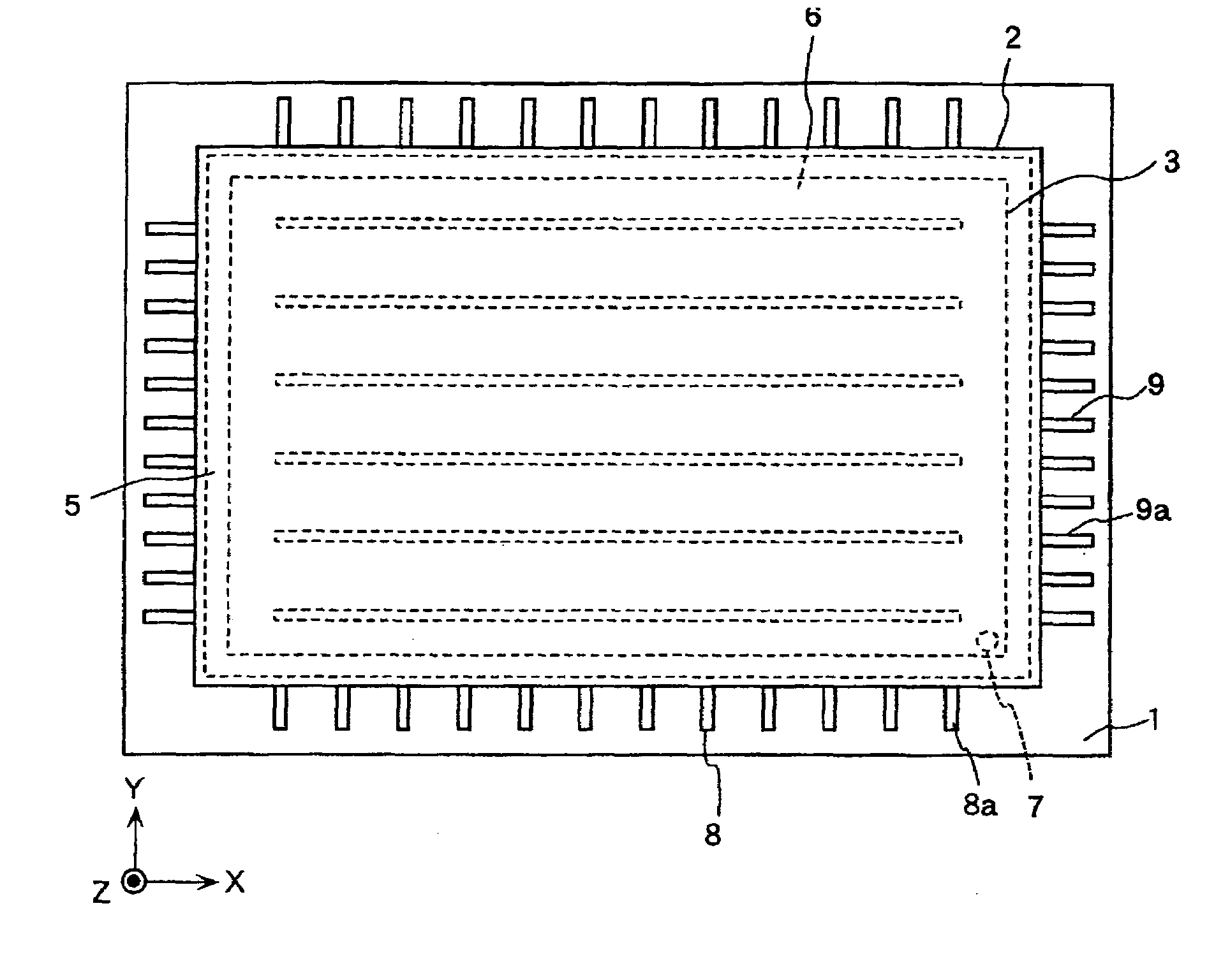
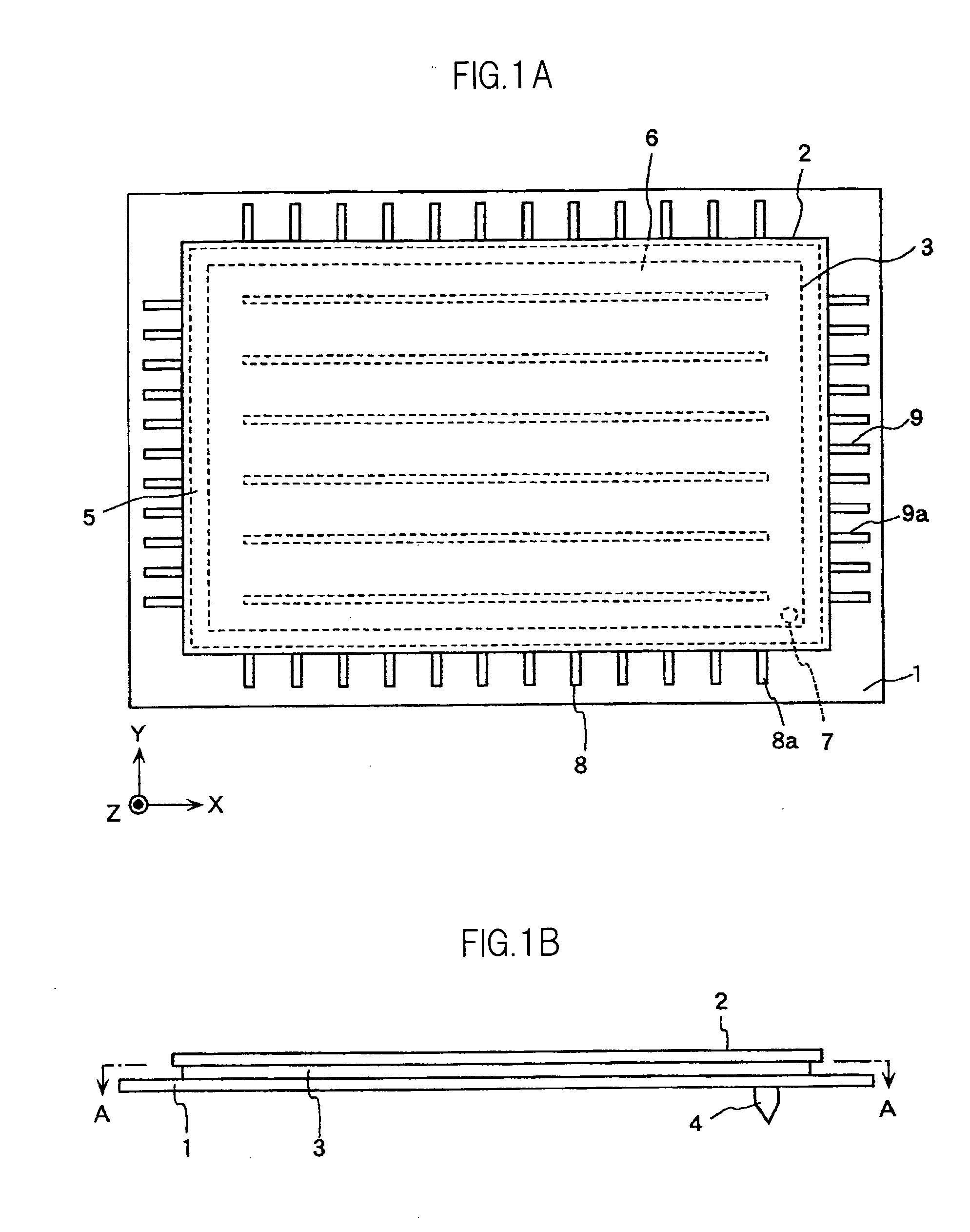
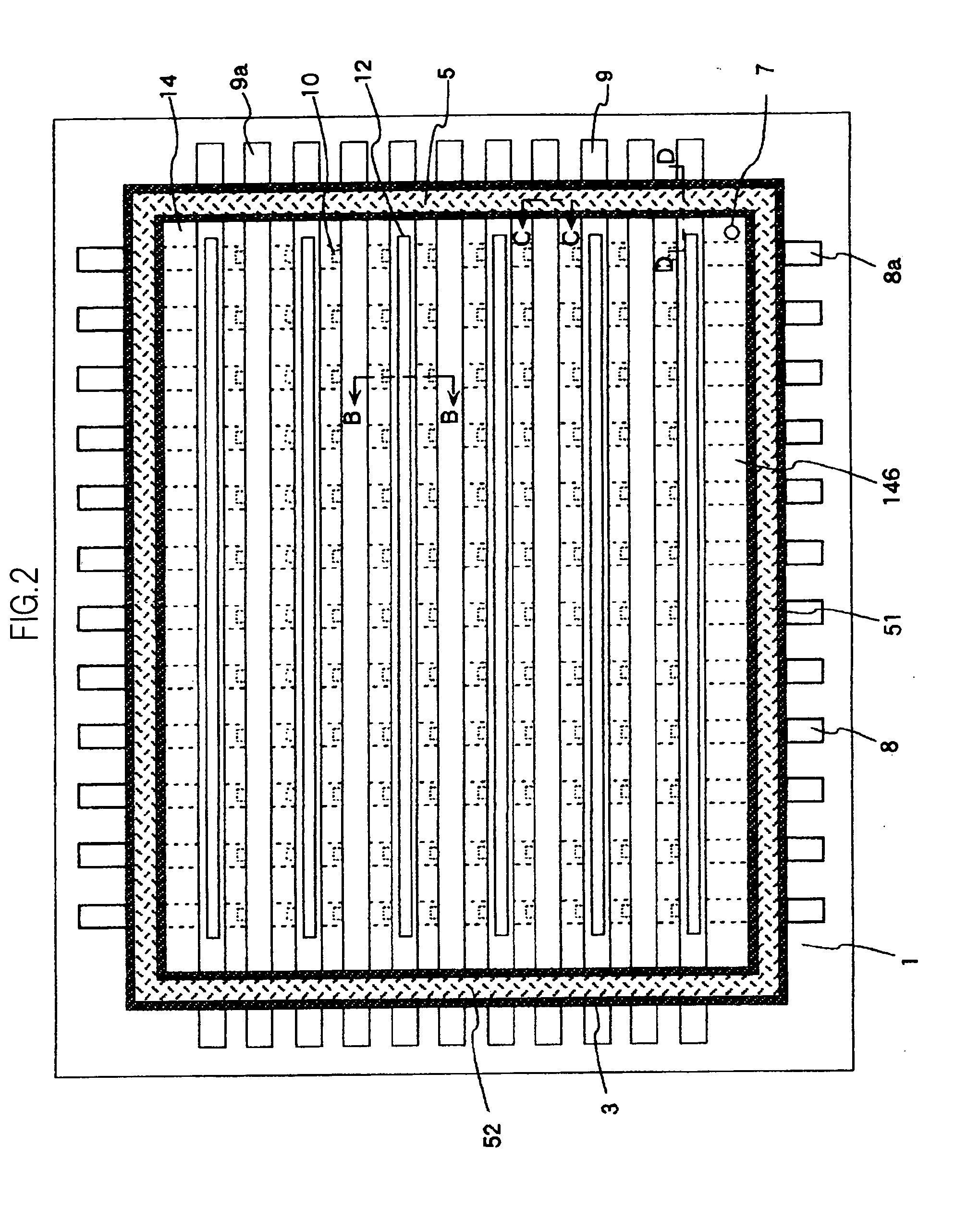
[0083]FIGS. 1A through 5 are schematic views for describing the configuration of an image display device according to an embodiment of the present invention, wherein FIG. 1A is a plan view, FIG. 1B is a side view of FIG. 1A, FIG. 2 is a cross-sectional view along the line A-A in FIG. 1B, FIG. 3 is a cross-sectional view of a front-surface substrate of the portion along the line B-B in FIG. 2 and of the portion corresponding to the back-surface substrate thereof, FIG. 4A is a cross-sectional view along the line C-C in FIG. 2, FIG. 4B is a cross-sectional view along the line D-D in FIG. 2, and FIG. 5 is a plan view showing an example of the insulating film pattern in FIG. 2.

[0084]As shown in FIGS. 1A through 5, the image display device according to the present embodiment includes a back-surface substrate 1, a front-surface substrate 2, a frame 3, a ventilation pipe 4, a ...


PUM


Abstract

An image display device comprising a back-surface substrate (1) having a plurality of first electrodes (8), an insulating film (14), a plurality of second electrodes (9), and an electron source (10); a front-surface substrate (2) having a fluorescent layer (15), and further having an anode for the application of an acceleration voltage; a frame (3) disposed between the front-surface substrate (2) and the back-surface substrate (1); and a sealing member (5) for sealing the frame (3) and the two substrates in an airtight manner in a sealed area (52). The second electrodes (9) cover the insulating film (14) disposed beneath these second electrodes (9) in at least the sealed area (52), and place the sealing member (5) and the insulating film (14) in a non-contact state.

Description

CROSS-REFERENCE TO RELATED APPLICATIONS[0001]The present application claims priority from Japanese application JP 2007-166552 filed on Jun. 25, 2007, the content of which is hereby incorporated by reference into this application.BACKGROUND OF THE INVENTION[0002]1. Field of the Invention[0003]The present invention relates to a self-luminous flat panel image display device, and more particularly relates to an image display device in which an electron source is arranged in the form of a matrix.[0004]2. Description of the Related Art[0005]Field emission image display devices (FED: field emission displays) and electron emission image display devices utilizing cold cathodes that can be finely integrated are known as one of the self-luminous flat panel displays (FPD) having an electron source that is arranged in the form of a matrix.[0006]Examples of cold cathodes include Spindt electron sources, surface-conductive electron sources, carbon nanotube electron sources, and thin film electron ...

Claims


Application Information

Patent Timeline
Patent Type & Authority Applications(United States)
IPC IPC(8): H01J63/04H01J9/24
CPCH01J9/32H01J2329/90H01J31/127H01J29/90
Inventor NAKAMURA, TOMOKIYANASE, HIROYASUKUSUNOKI, TOSHIAKINISHIMURA, ETSUKO
Owner HITACHI LTD
Why Eureka
Try Eureka