Image display apparatus

a technology of image display and display screen, which is applied in the direction of instruments, computing, electric digital data processing, etc., can solve the problems of reducing the contrast caused by light leakage from unable to obtain sufficient and the light modulating device does not have ideal modulation characteristics, etc., to achieve the effect of further enhancing the visual contrast of the input imag

Inactive Publication Date: 2009-01-01
KK TOSHIBA
View PDF15 Cites 95 Cited by
  • Summary
  • Abstract
  • Description
  • Claims
  • Application Information

AI Technical Summary

Benefits of technology

[0015]According to the embodiments of the invention, the visual contrast of the input image can further be enhanced.

Problems solved by technology

However, in these image display apparatuses, the light modulating device does not have ideal modulation characteristics.
Therefore, lowering of contrast caused by light leak from the light modulating device occurs especially when black image is displayed.
However, images which are significantly different in gray-scale distribution even though these representative values are the same exist in abundance, and there is a problem that sufficient contrast of the input image cannot be obtained since the same light source luminance and the gamma conversion are set up for all the images in the related art.

Method used


Image

  • Image display apparatus
  • Image display apparatus
  • Image display apparatus

Examples


first embodiment

[0034]Referring now to FIG. 1 to FIG. 17, an image display apparatus 10 according to a first embodiment of the invention will be described.

(1) Configuration of Image Display Apparatus 10

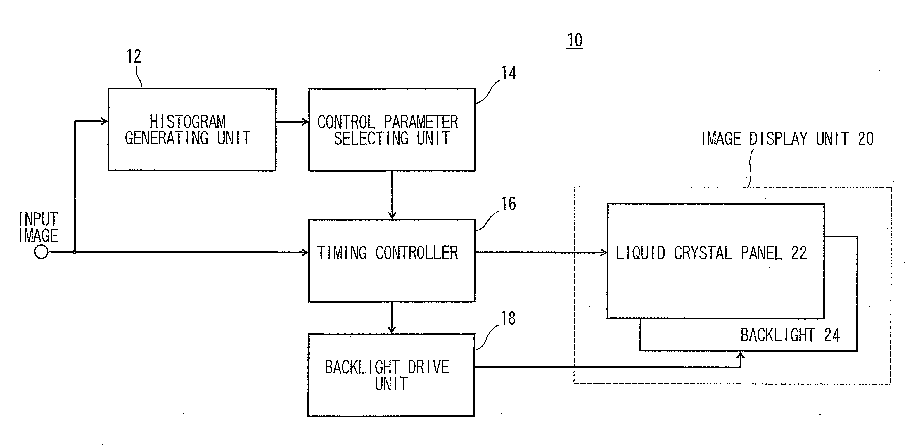
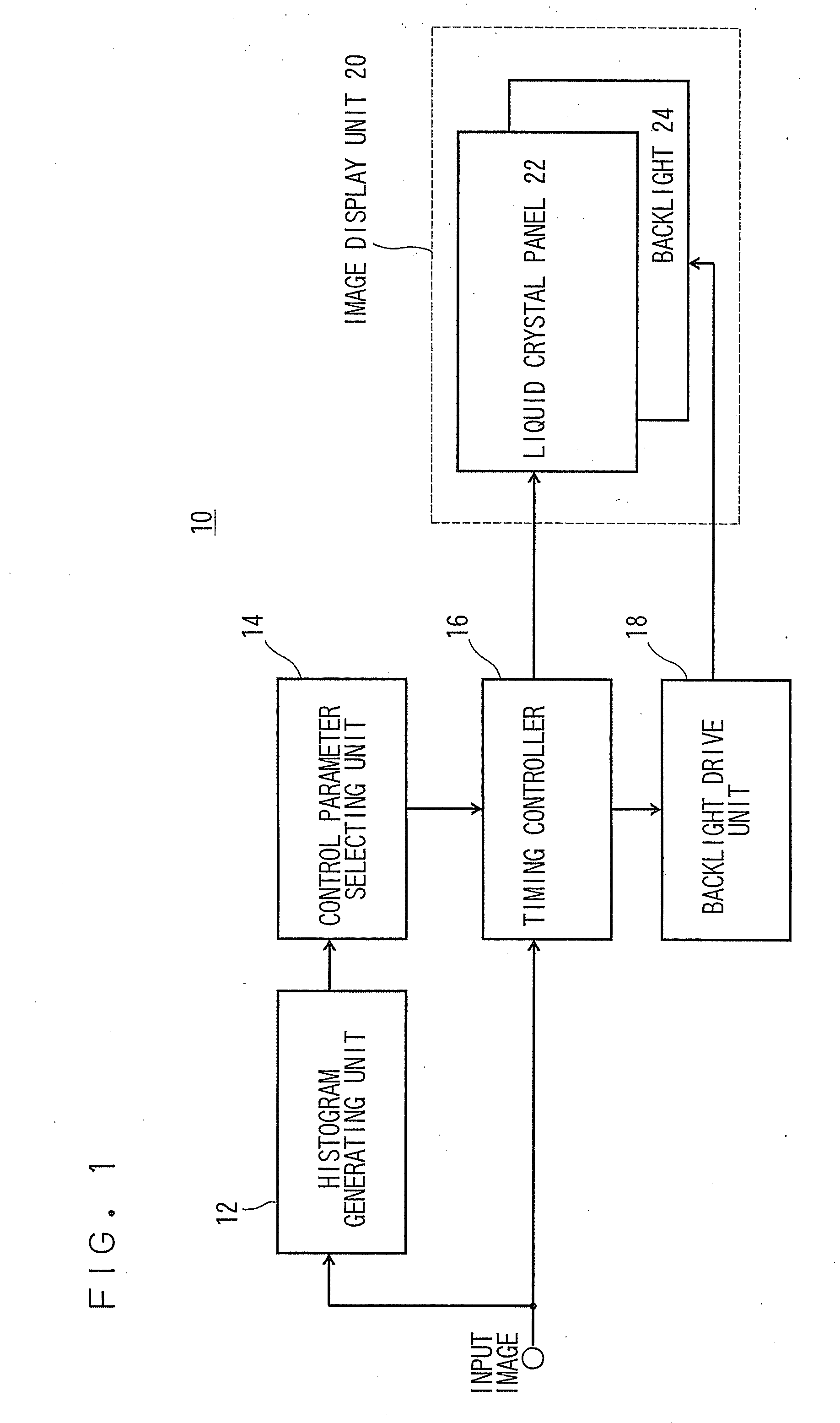
[0035]FIG. 1 shows a configuration of the image display apparatus 10 according to the first embodiment.

[0036]The image display apparatus 10 includes a histogram generating unit 12, a control parameter selecting unit 14, a timing controller 16 as a control unit, a backlight drive unit 18 and an image display unit 20.

[0037]The image display unit 20 includes a liquid crystal panel 22 as a light modulating unit and a backlight 24 as a light source installed on the back side of the liquid crystal panel 22.

[0038]The input image is supplied to the histogram generating unit 12 and the timing controller 16.

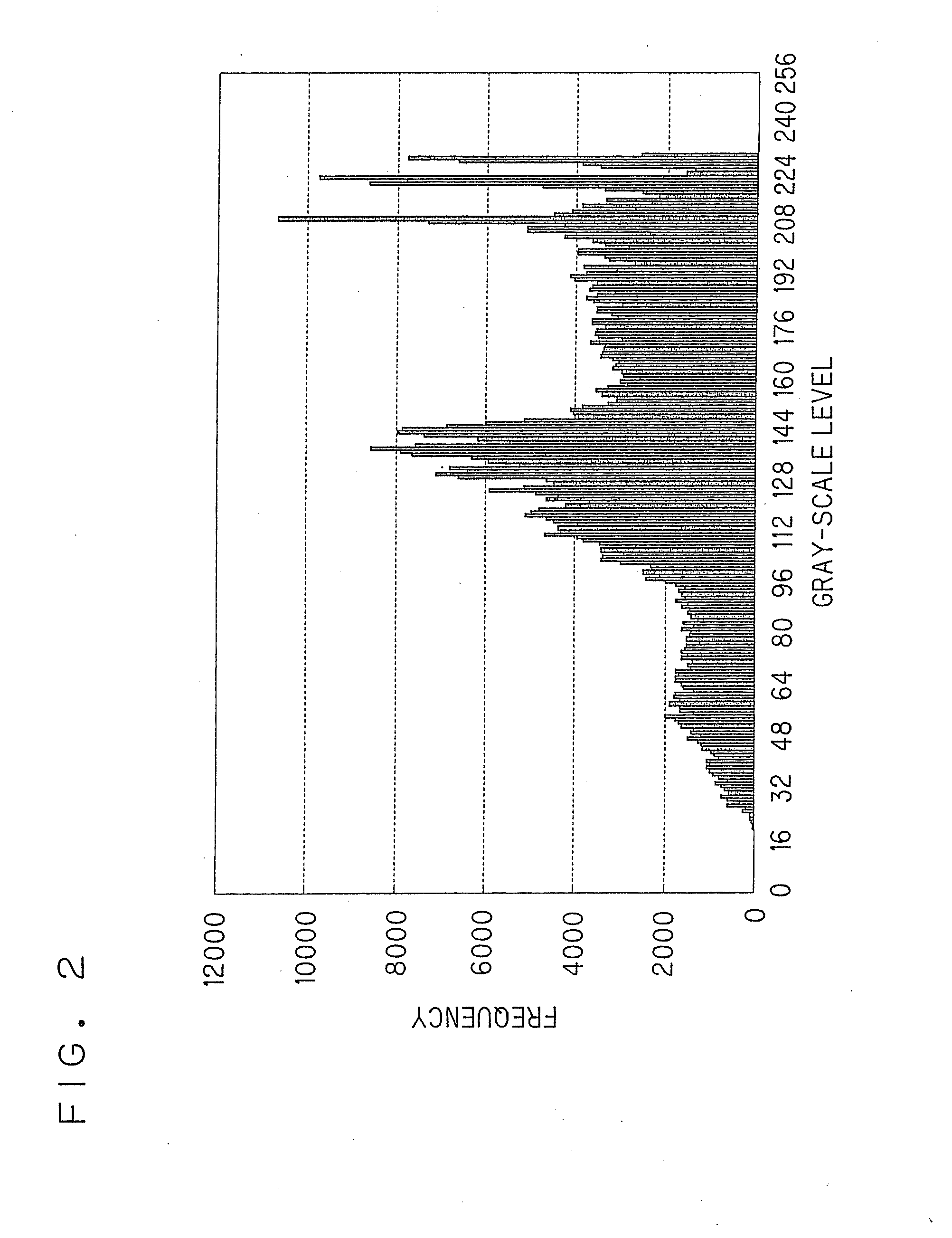
[0039]The histogram generating unit 12 counts the number of pixels included in each of predetermined gray-scale level ranges in the input image and generates a histogram showing the representative gray-scal...

modification 3

(2-3) Modification 3

[0050]In a case in which the type of the input image is composed of three channels of Y, Cb and Cr (hereinafter referred to as Y Cb Cr input image), which are composed of the luminance and the color difference signal, a configuration to generate the histogram of Y, which is a luminance channel, may be employed.

modification 4

(2-4) Modification 4

[0051]A configuration to generate the histogram as described above after having converted the Y Cb Cr input image into the RGB image according to the expression 2 may also be employed.

[RGB]=[1.00000.00001.40201.0000-0.3441-0.71411.00001.77200.0000][YCb-128Cr-128](2)

where Y, Cb and Cr are values of the luminance and the color difference signal normalized into 8-bits, and R, G and B are values of the image signal composed of three channels of red, green and blue normalized into 8-bits.

[0052]The expression 2 is an example of conversion, and other coefficients of conversion may also be used.


PUM


Abstract

An image display apparatus includes an image display unit having a light source and a light modulating unit; a histogram generating unit; a function generating unit; a first brightness calculating unit; a second brightness calculating unit; a first difference calculating unit; a first multiplying unit; a first summation calculating unit; a first brightness gradient calculating unit; a second brightness gradient calculating unit; a second difference calculating unit; a second multiplying unit; a second summation calculating unit; a weighted linear sum calculating unit; a determination unit; a control parameter selecting unit; and a control unit.

Description

CROSS-REFERENCE TO RELATED APPLICATIONS[0001]This application is based upon and claims the benefit of priority from the prior Japanese Patent Application No. 2007-170623, filed on Jun. 28, 2007; the entire contents of which are incorporated herein by reference.BACKGROUND OF THE INVENTION[0002]1. Field of the Invention[0003]The present invention relates to an image display apparatus and a method which achieve enhancement of visual contrast of displayed images.[0004]2. Description of the Related Art[0005]In recent yeas, an image display apparatus provided with a light source and a light modulating device that modulates the intensity of light from the light source is widely used.[0006]A representative example is a liquid crystal display apparatus. However, in these image display apparatuses, the light modulating device does not have ideal modulation characteristics. Therefore, lowering of contrast caused by light leak from the light modulating device occurs especially when black image ...

Claims


Application Information

Patent Timeline
Patent Type & Authority Applications(United States)
IPC IPC(8): G09G3/30
CPCG09G3/3406G09G3/3611G09G2320/0646G09G2360/16G09G2320/066G09G2320/0673G09G2320/103G09G2320/0653G09G3/36G09G3/20G02F1/133
Inventor BABA, MASAHIROITOH, GOH
Owner KK TOSHIBA
Why Eureka
Try Eureka