
Image to temporal pixel mapping

a technology of image and pixel, applied in the field of image to temporal pixel mapping, can solve the problems of large display cost, large display size, and large display resolution of digital displays using liquid crystal display or plasma technology

Inactive Publication Date: 2009-01-01
SNAPTRACK
View PDF100 Cites 16 Cited by
  • Summary
  • Abstract
  • Description
  • Claims
  • Application Information

AI Technical Summary

Benefits of technology

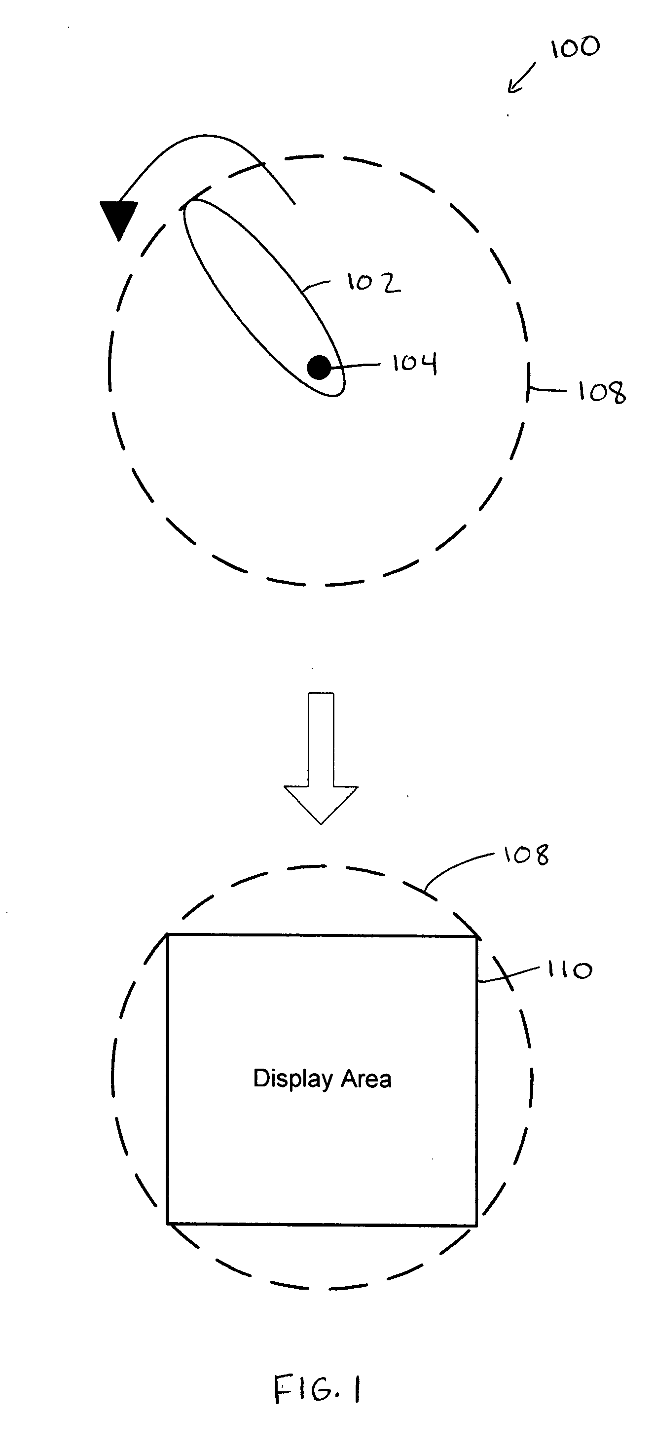
The invention is about improving digital displays by using a composite display with multiple paddles. These paddles can rotate to create a larger display. The paddles have pixels and a cooling system to prevent overheating. The invention also includes a system for displaying images using these composite displays. The technical effects of the invention include larger displays, improved resolution, and reduced costs.

Problems solved by technology

Digital displays that use liquid crystal display (LCD) or plasma technologies are limited in size because of size limits of the glass panels associated with these technologies.
Because of the space required by the LEDs, the resolution of these displays is relatively coarse.
Also, each LED corresponds to a pixel in the image, which can be expensive for large displays.
In addition, a complex cooling system is typically used to sink heat generated by the LEDs, which may burn out at high temperatures.

Method used


Image

  • Image to temporal pixel mapping
  • Image to temporal pixel mapping
  • Image to temporal pixel mapping

Examples


Embodiment Construction

[0026]The invention can be implemented in numerous ways, including as a process, an apparatus, a system, a composition of matter, a computer readable medium such as a computer readable storage medium or a computer network wherein program instructions are sent over optical or communication links. In this specification, these implementations, or any other form that the invention may take, may be referred to as techniques. A component such as a processor or a memory described as being configured to perform a task includes both a general component that is temporarily configured to perform the task at a given time or a specific component that is manufactured to perform the task. In general, the order of the steps of disclosed processes may be altered within the scope of the invention.

[0027]A detailed description of one or more embodiments of the invention is provided below along with accompanying figures that illustrate the principles of the invention. The invention is described in conne...


PUM


Abstract

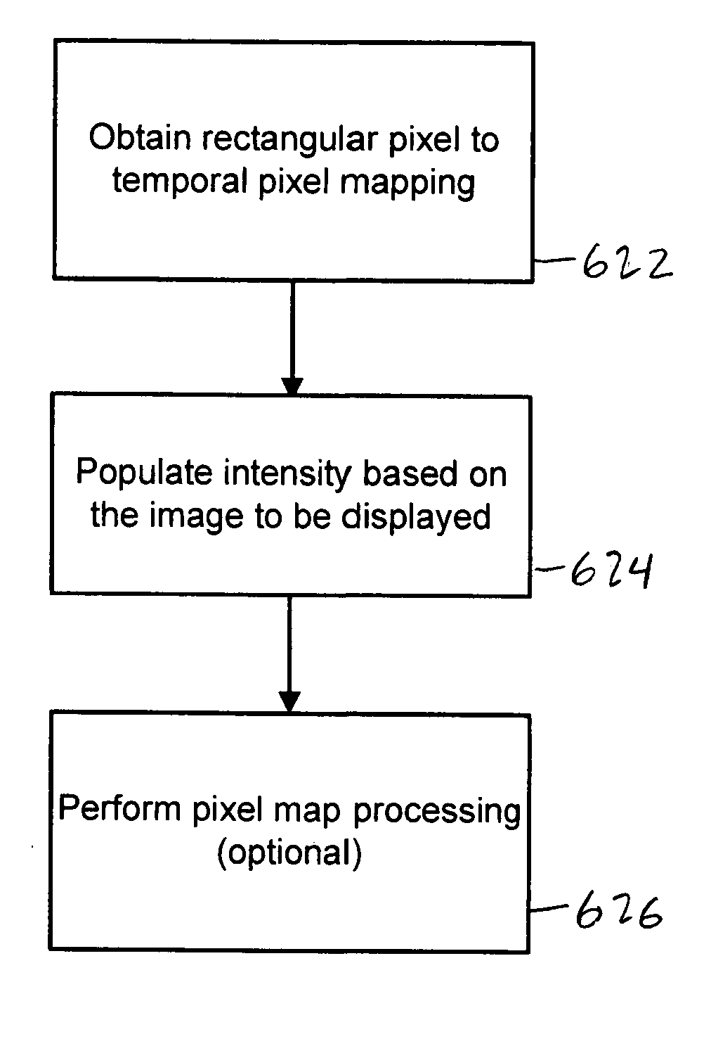
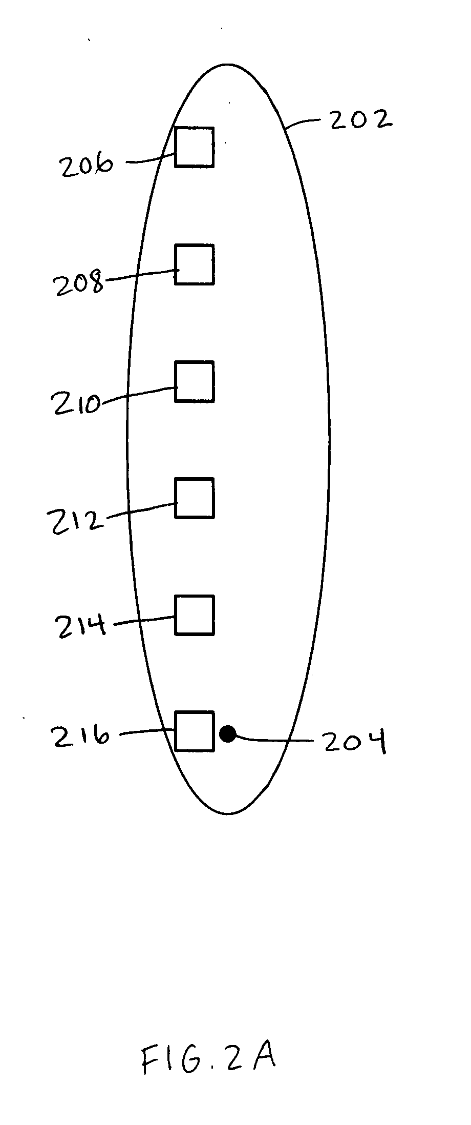
Image pixel to temporal pixel mapping is disclosed. In some embodiments, a grid of stochastically arranged temporal pixels is employed in a composite display. An image pixel may be mapped to one or more temporal pixels in the grid. One or more of the one or more temporal pixels in the grid to which the image pixel is mapped are employed to render the image pixel in the composite display.

Description

CROSS REFERENCE TO OTHER APPLICATIONS[0001]This application claims priority to U.S. Provisional Patent Application No. ______ (Attorney Docket No. BOUNP001) entitled COMPOSITE DISPLAY filed Jun. 28, 2007, originally filed as non-provisional U.S. patent application Ser. No. 11 / 823,829 and subsequently converted to a provisional application by request submitted Oct. 1, 2007, which application is incorporated herein by reference for all purposes.BACKGROUND OF THE INVENTION[0002]Digital displays are used to display images or video to provide advertising or other information. For example, digital displays may be used in billboards, bulletins, posters, highway signs, and stadium displays. Digital displays that use liquid crystal display (LCD) or plasma technologies are limited in size because of size limits of the glass panels associated with these technologies. Larger digital displays typically comprise a grid of printed circuit board (PCB) tiles, where each tile is populated with packag...

Claims


Application Information

Patent Timeline
Patent Type & Authority Applications(United States)
IPC IPC(8): G06F17/00
CPCG09G3/005G09G3/32G09F19/12G09F9/33G09F9/37G09G2300/026
Inventor CHUI, CLARENCE
Owner SNAPTRACK
Learn More