
Actuator unit and manufacturing method thereof, and liquid ejection head

a technology of liquid ejection and actuator, which is applied in the direction of printing and inking apparatus, etc., can solve the problems of reducing printing quality, increasing or decreasing the quantity of ink ejection, and reducing the application of external electric fields to the portion of piezoelectric layer, etc., to achieve higher-speed printing, increase image resolution, and reduce the effect of ink ejection quantity

Inactive Publication Date: 2009-01-01
BROTHER KOGYO KK
View PDF8 Cites 14 Cited by
  • Summary
  • Abstract
  • Description
  • Claims
  • Application Information

AI Technical Summary

Benefits of technology

[0007]Recently in such an inkjet head as described above, pressure chambers are arranged at a higher density in order to meet the requirements of an increase in image resolution and higher-speed printing. However, this brings about a problem of so-called structural crosstalk in which deformation of an active portion opposed to a pressure chamber causes deformation of a portion of the piezoelectric sheet opposed to a neighboring pressure chamber so that the quantity of ink ejection is increased or decreased from its desired quantity. In particular, as for a land formed as an extension from each individual electrode for inputting a voltage to the individual electrode through the land, which land is positioned so as to be opposed to a region of the piezoelectric sheet outside the corresponding pressure chamber, that is, so as not to be opposed to the corresponding pressure chamber, such a land was conventionally considered not to be a factor of occurrence of crosstalk because it does not directly drive the corresponding pressure chamber. However, the inventors of the present invention have found that such a land can be a factor of occurrence of crosstalk because the portion of the piezoelectric sheet sandwiched by the land and the common electrode is also deformed by an applied external electric field so as to deform a portion of the piezoelectric sheet around the land. The inventors of the present invention have further found that such a land has no measurable effect because the land is positioned closer to a neighboring pressure chamber than the corresponding individual electrode. When such structural crosstalk occurs, the quantity of deformation of the piezoelectric sheet overlapping each pressure chamber differs from the desired quantity so that ink ejection characteristics such as ink droplet velocity and ink droplet volume vary. This reduces printing quality.
[0008]An object of the present invention is to provide an actuator unit, a manufacturing method of the unit, and a liquid ejection head, wherein structural crosstalk can be reduced.
[0010]According to the above aspect of the invention, the plurality of electric field blocking layers each having one or more holes are interposed between the piezoelectric layer and the plurality of lands. Thus, when a plurality of lands and a plurality of individual electrodes and the common electrode are put at predetermined potentials, an external electric field is hard to be applied to the portion of the piezoelectric layer opposed to each land. Therefore, the portion of the piezoelectric layer is hard to be deformed. This suppresses so-called structural crosstalk in which the deformation of the portion of the piezoelectric layer spreads around the portion. In addition, because each electric field blocking layer has one or more holes, its dielectric constant is lower than that of the piezoelectric layer. This expands the scope of selection of the raw material of the base material of the electric field blocking layer.
[0012]According to the above aspect of the invention, the plurality of electric field blocking layers each having one or more holes can be formed between the piezoelectric layer and the plurality of lands. Thus, an actuator unit having the following effect can be manufactured. That is, when a plurality of lands and a plurality of individual electrodes and the common electrode are put at predetermined potentials, an external electric field is hard to be applied to the portion of the piezoelectric layer opposed to each land. Therefore, the portion of the piezoelectric layer is hard to be deformed. This suppresses so-called structural crosstalk in which the deformation of the portion of the piezoelectric layer spreads around the portion.
[0014]According to the above aspect of the invention, a porous electric field blocking layer is interposed between each land and the piezoelectric layer. Thus, when a plurality of lands and a plurality of individual electrodes and the common electrode are put at predetermined potentials, an external electric field is hard to be applied to the portion of the piezoelectric layer opposed to each land. Therefore, the portion of the piezoelectric layer is hard to be deformed. This suppresses so-called structural crosstalk in which the deformation of the portion of the piezoelectric layer spreads around the portion. As a result, liquid ejection characteristics become stable. In addition, because each electric field blocking layer is porous, its dielectric constant is lower than that of the piezoelectric layer. This expands the scope of selection of the raw material of the base material of the electric field blocking layer.

Problems solved by technology

However, this brings about a problem of so-called structural crosstalk in which deformation of an active portion opposed to a pressure chamber causes deformation of a portion of the piezoelectric sheet opposed to a neighboring pressure chamber so that the quantity of ink ejection is increased or decreased from its desired quantity.
This reduces printing quality.
Thus, when a plurality of lands and a plurality of individual electrodes and the common electrode are put at predetermined potentials, an external electric field is hard to be applied to the portion of the piezoelectric layer opposed to each land.
Therefore, the portion of the piezoelectric layer is hard to be deformed.

Method used


Image

  • Actuator unit and manufacturing method thereof, and liquid ejection head
  • Actuator unit and manufacturing method thereof, and liquid ejection head
  • Actuator unit and manufacturing method thereof, and liquid ejection head

Examples


Embodiment Construction

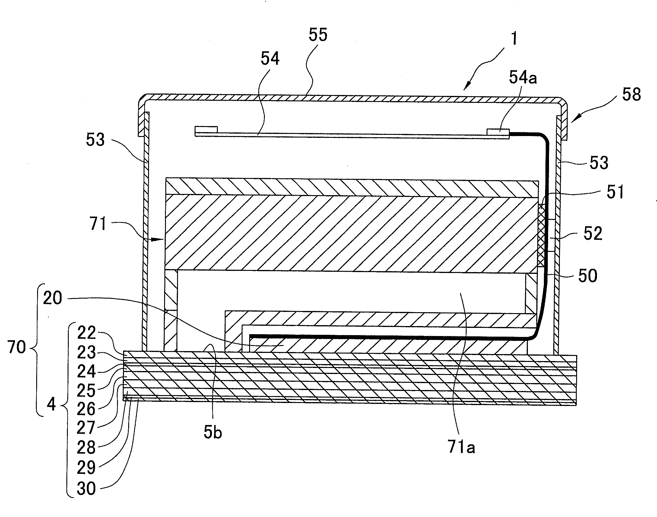
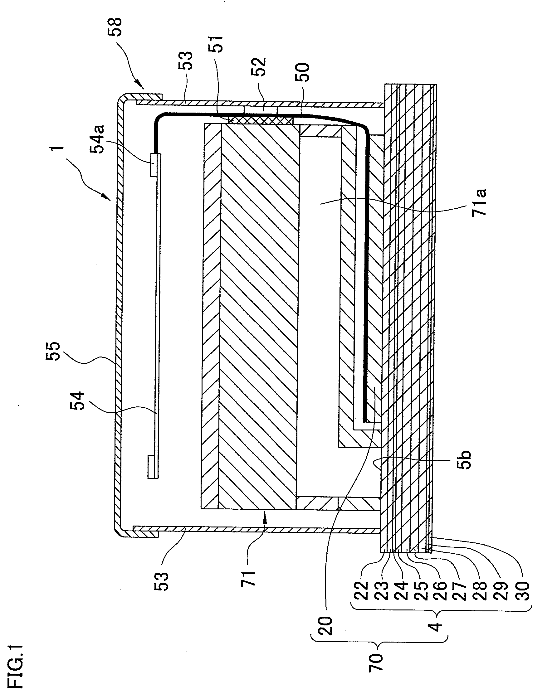
[0026]An inkjet head according to a first embodiment of the present invention will be described. As shown in FIG. 1, the inkjet head 1 as a liquid ejection head includes a head main body 70 that ejects ink; a reservoir unit 71 positioned on an upper face of the head main body 70; flexible printed circuits (FPCs) 50 electrically connected to the head main body 70; and a control substrate 54 electrically connected to the FPCs 50. Of them, the head main body 70 is made up of a passage unit 4 in which ink passages are formed; and actuator units 20. The reservoir unit 71 supplies ink to the passage unit 4. Each FPC 50 is connected at its one end to an upper face of the corresponding actuator unit 20. In the middle of each FPC 50, a driver IC 52 is provided for supplying a drive signal.

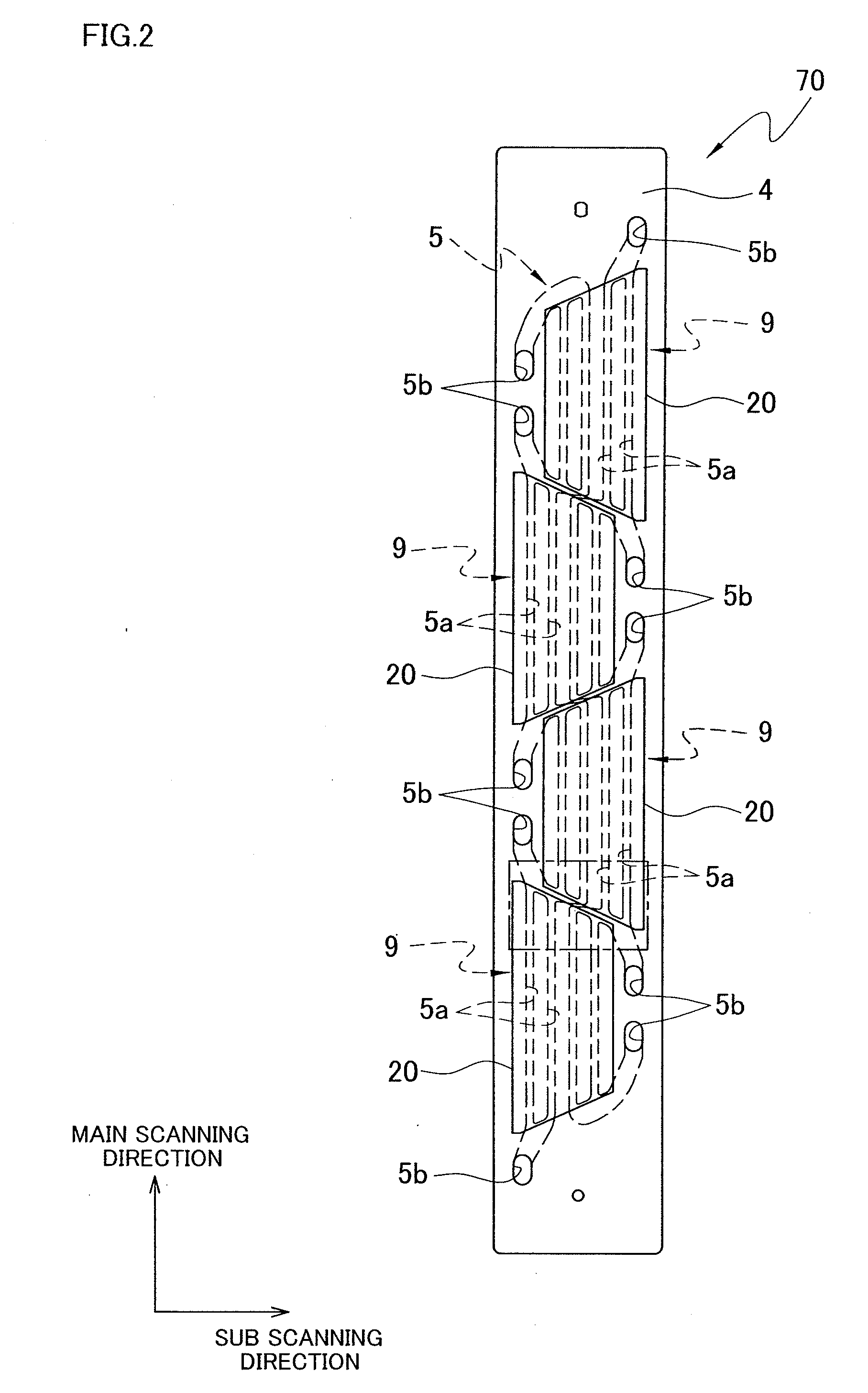
[0027]As shown in FIG. 2, the head main body 70 has at the upper face of the passage unit 4 ten ink supply ports 5b connected to the internal ink passages. As will be described later, each ink passage inclu...


PUM


Abstract

An actuator unit for applying pressure to liquid in each of pressure chambers formed in a passage unit includes a piezoelectric layer; a common electrode formed on one surface of the piezoelectric layer to be positioned over the pressure chambers; and electric field blocking layers formed on an opposite surface of the piezoelectric layer from the one surface to be opposed to the common electrode and outside regions of the respective pressure chambers. Each electric field blocking layer is porous and lower in dielectric constant than the piezoelectric layer. The actuator unit further includes lands each positioned to sandwich an electric field blocking layer between the land and the piezoelectric layer; and individual electrodes formed on the opposite surface to be opposed to the respective pressure chambers and the common electrode and neighbor the respective electric field blocking layers. Each individual electrode is electrically connected to the corresponding land.

Description

[0001]The present application claims priority from Japanese Patent Application No. 2007-171356, which was filed on Jun. 29, 2007, the disclosure of which is herein incorporated by reference in its entirety.BACKGROUND OF THE INVENTION[0002]1. Field of the Invention[0003]The present invention relates to an actuator unit to be used in a liquid ejection head that ejects liquid, a manufacturing method of the actuator unit, and the liquid ejection head.[0004]2. Description of Related Art[0005]In an inkjet head as a liquid ejection head of an inkjet printer, ink supplied from an ink tank is distributed to a plurality of pressure chambers. Pulsed pressure is then selectively applied to the pressure chambers to eject ink from nozzles. As a means for selectively applying pressure to ink in pressure chambers, an actuator unit can be used in which a plurality of piezoelectric layers made of piezoelectric ceramic are put in layers.[0006]For example, Japanese Patent Unexamined Publication No. Hei...

Claims


Application Information

Patent Timeline
IPC IPC(8): B41J2/045
CPCB41J2/14209B41J2/1609B41J2/1623B41J2/1629B41J2/1631B41J2202/20B41J2002/14217B41J2002/14225B41J2002/14306B41J2002/14459B41J2002/14491B41J2/1646
Inventor OKAWA, YASUOSAKAIDA, ATSUO
Owner BROTHER KOGYO KK
Learn More