Image Projection System and Image Geometric Correction Device

Inactive Publication Date: 2009-01-01
MITSUBISHI ELECTRIC CORP
View PDF4 Cites 32 Cited by
  • Summary
  • Abstract
  • Description
  • Claims
  • Application Information

AI Technical Summary

Benefits of technology

[0010]Therefore, the present invention offers an advantage of being able to divide an image on the whole screen into two or more part images and then capture them, and to make a geometric correction to the projected images, without strictly placing the image capturing devices at predetermined positions.

Problems solved by technology

A problem with the prior art image projection system constructed as mentioned above is that it is necessary to strictly place an image capturing device at a predetermined position in order to capture, as a single image, images projected onto a whole screen in a state in which all image projection devices project the images on the screen.

Method used


Image

  • Image Projection System and Image Geometric Correction Device
  • Image Projection System and Image Geometric Correction Device
  • Image Projection System and Image Geometric Correction Device

Examples


embodiment 1

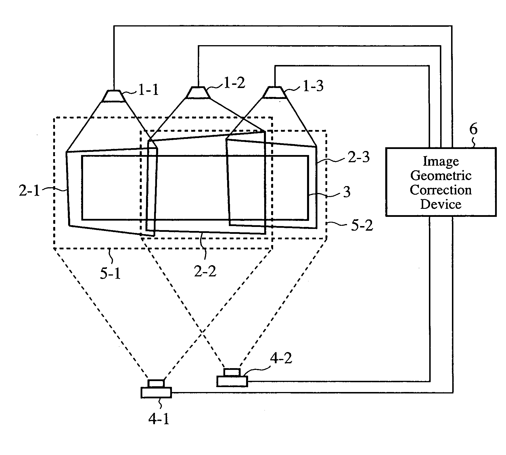
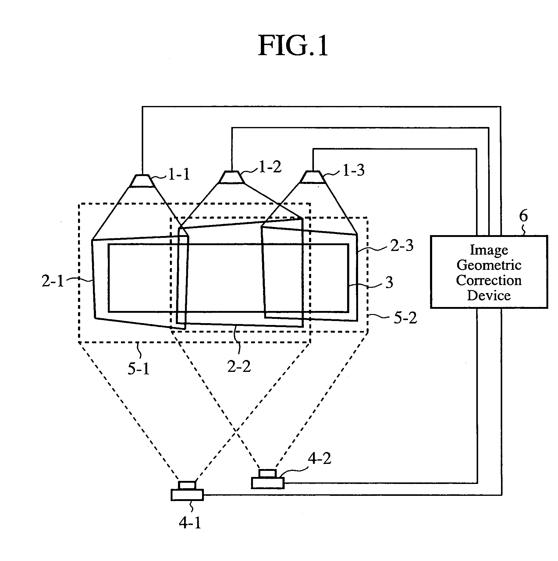
[0024]FIG. 1 is a block diagram showing an image projection system in accordance with embodiment 1 of the present invention. In the figure, an image projection device 1-1 projects an image 2-1 which is a part image on a left-hand section of a screen 3, and an image projection device 1-2 projects an image 2-2 which is a part image on a central section of the screen 3. Furthermore, an image projection device 1-3 projects an image 2-3 which is a part image on a right-hand section of the screen 3.

[0025]An image capturing device 4-1 captures an image region to be captured 5-1 which includes the images 2-1 and 2-2 respectively projected by the image projection devices 1-1 and 1-2, and an image capturing device 4-2 captures an image region to be captured 5-2 which includes the images 2-2 and 2-3 respectively projected by the image projection devices 1-2 and 1-3.

[0026]An image geometric correction device 6 unifies the coordinate systems of the images captured by the image capturing devices ...

embodiment 2

[0093]In above-mentioned embodiment 1, the image projection devices 1-1, 1-2, 1-3 and the image capturing devices 4-1 and 4-2 are disposed, as mentioned above. In this embodiment, as shown in FIG. 7, image projection devices 1-4 and 1-5 and image capturing devices 4-3 and 4-4 are additionally disposed, and the indication unit 11 of the image geometric correction device 6 sets up a combination of the image projection device 1-3 and image capturing device 4-3, in addition to the following combinations.

[0094]A combination of the image projection device 1-4 and image capturing device 4-3

[0095]A combination of the image projection device 1-4 and image capturing device 4-4

[0096]A combination of the image projection device 1-5 and image capturing device 4-3

[0097]A combination of the image projection device 1-5 and image capturing device 4-4

[0098]In this case, the storage unit 13 of the image geometric correction device 6 stores images and deformation movement conversion data as shown in FI...

embodiment 3

[0100]In above-mentioned embodiment 1, an example in which the two image capturing devices 4-1 and 4-2 are disposed is shown. In a case in which the image capturing device 4-1 consists of a movable camera or the like, the image capturing device 4-1 is properly moved so that the image capturing device 4-1 can capture the image region to be captured 5-1 and image region to be captured 5-2, as shown in FIG. 9.

[0101]Even in this case, the same advantage as provided by above-mentioned embodiment 1 can be offered. Furthermore, this embodiment offers another advantage of being able to reduce the cost of constructing the image projection system by the image capturing device 4-2 which becomes unnecessary.


PUM


Abstract

An image geometric correction device 6 unifies the coordinate systems of images captured by image capturing devices 4-1 and 4-2 into a coordinate system, and makes a geometric correction to the images projected by image projection devices 1-1, 1-2, and 1-3 on the basis of an image projection region E in the coordinate system into which the coordinate systems of the captured images are unified. As a result, the image geometric correction device can make a geometric correction to the projected images without strictly placing the image capturing devices 4-1 and 4-2 at predetermined positions.

Description

FIELD OF THE INVENTION[0001]The present invention relates to an image projection system which connects part images projected by two or more image projection devices to one another on one screen so as to display a single image, and an image geometric correction device which makes a geometric correction to each of the part images so that the part images projected by the two or more image projection devices can be smoothly connected to one another at their connection regions.BACKGROUND OF THE INVENTION[0002]An image projection system which connects images projected by two or more image projection devices on one screen to one another to generate a single image, and displays the single image needs to move the positions of the projected images and to deform the projected images so that the projected images can be smoothly connected to one another at their connection points. Generally, this movement processing and deformation processing are called a geometric correction.[0003]Because it is...

Claims


Application Information

Patent Timeline
Patent Type & Authority Applications(United States)
IPC IPC(8): G03B21/26
CPCH04N9/3147H04N9/3197H04N9/3194H04N9/3185
Inventor HARADA, MASAYUKI
Owner MITSUBISHI ELECTRIC CORP
Why Eureka
Try Eureka