
Asyncronous broadcast for ordered delivery between compute nodes in a parallel computing system where packet header space is limited

Inactive Publication Date: 2009-01-01
IBM CORP
View PDF5 Cites 98 Cited by
  • Summary
  • Abstract
  • Description
  • Claims
  • Application Information

AI Technical Summary

Benefits of technology

[0017]It is therefore an object of the present invention to provide a novel technique and method for providing asynchronous broadcasts where ordered delivery of data packets is maintained between compute nodes in the parallel computing system where packet header space is limited.

Problems solved by technology

This is typically enforced in hardware, or in software through a barrier before each broadcast operation, which results in larger overheads for short messages.
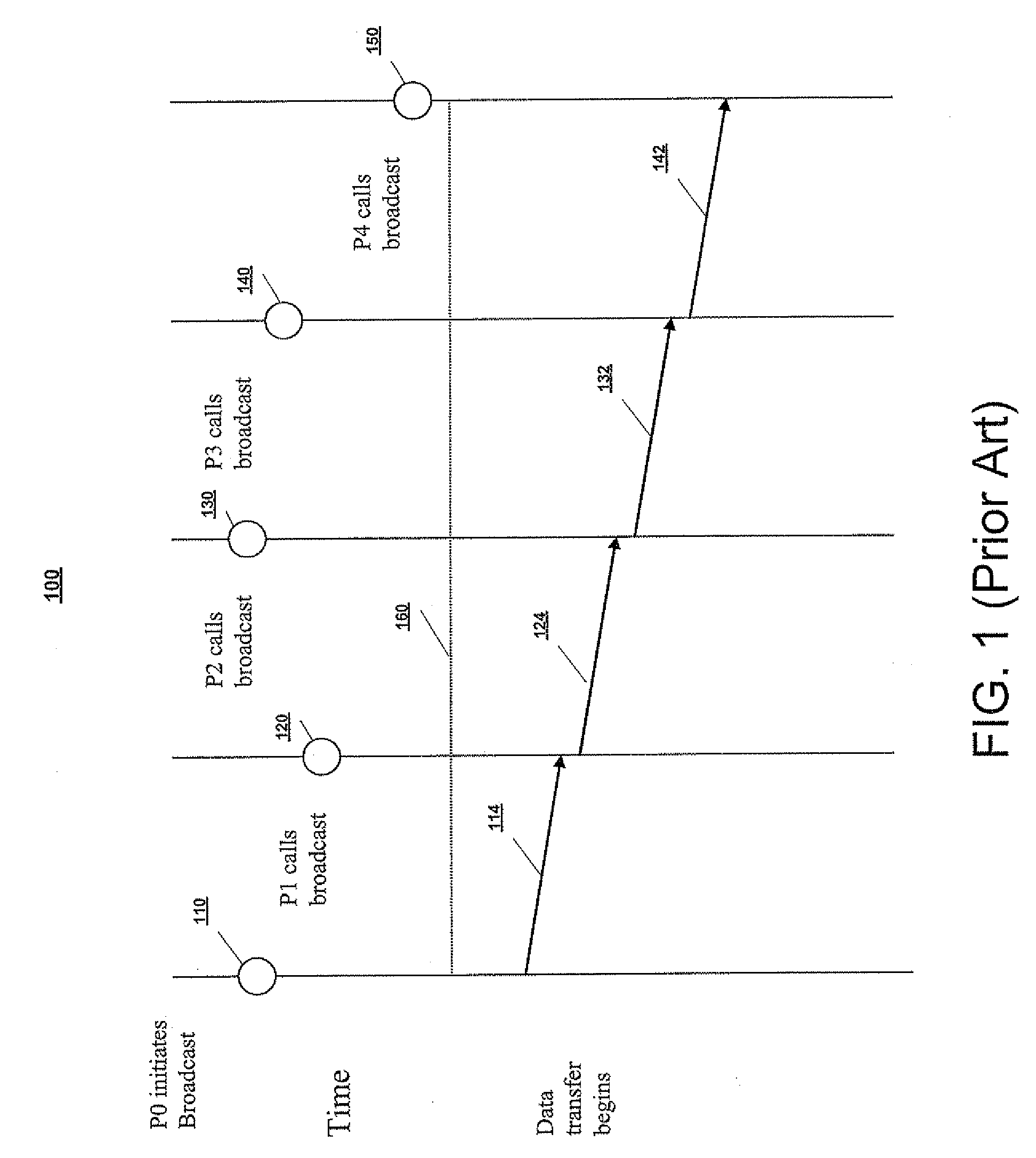
However, there is no known mechanism on the receiving compute nodes in the communicator to provide order or context to the data packets and to distinguish data packets from several incoming asynchronous broadcast messages.

Method used


Image

  • Asyncronous broadcast for ordered delivery between compute nodes in a parallel computing system where packet header space is limited
  • Asyncronous broadcast for ordered delivery between compute nodes in a parallel computing system where packet header space is limited
  • Asyncronous broadcast for ordered delivery between compute nodes in a parallel computing system where packet header space is limited

Examples


Embodiment Construction

[0041]Hereinafter, embodiments of the present invention will be described in detail with reference to the accompanying drawings. For the purposes of clarity and simplicity, a detailed description of known functions and configurations incorporated herein will be omitted as it may make the subject matter of the present invention unclear.

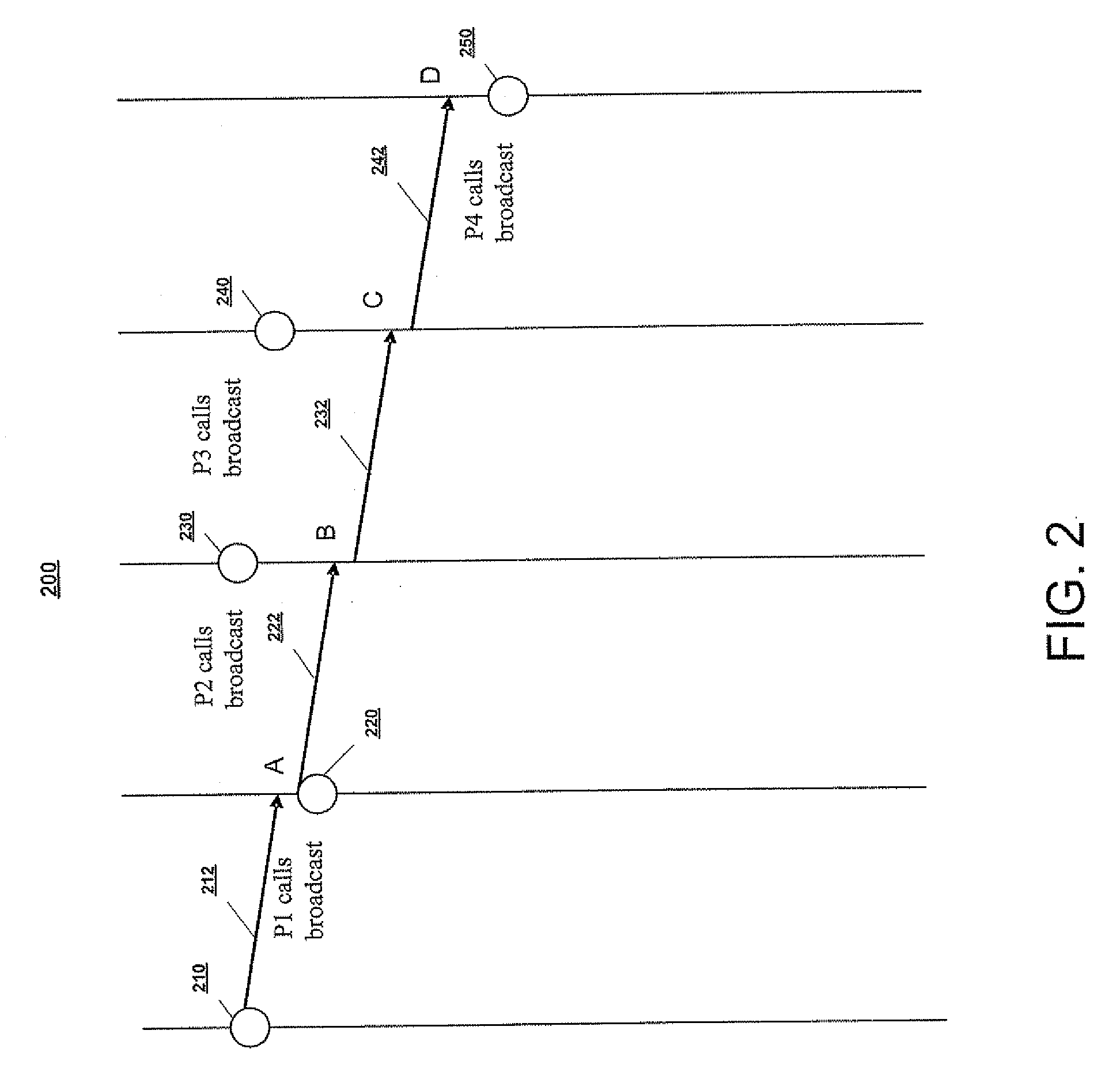
[0042]Referring to FIG. 2 is an example of an illustration of an asynchronous broadcast call on a communicator 200 in accordance with the present invention. As can been seen in FIG. 2, all processors 210, 220, 230, 240 and 250 begin their data transfers before all processors complete the broadcast call. In other words, data packets moves to all other destination nodes independent of when the processors initiate broadcasts. As can be seen in FIG. 2, a broadcast message may need to be handled unexpectedly on destination nodes P1210 and P4250. For example, processor P1210 completes its data transfer at position A before P4250 calls the broadcast at positi...


PUM


Abstract

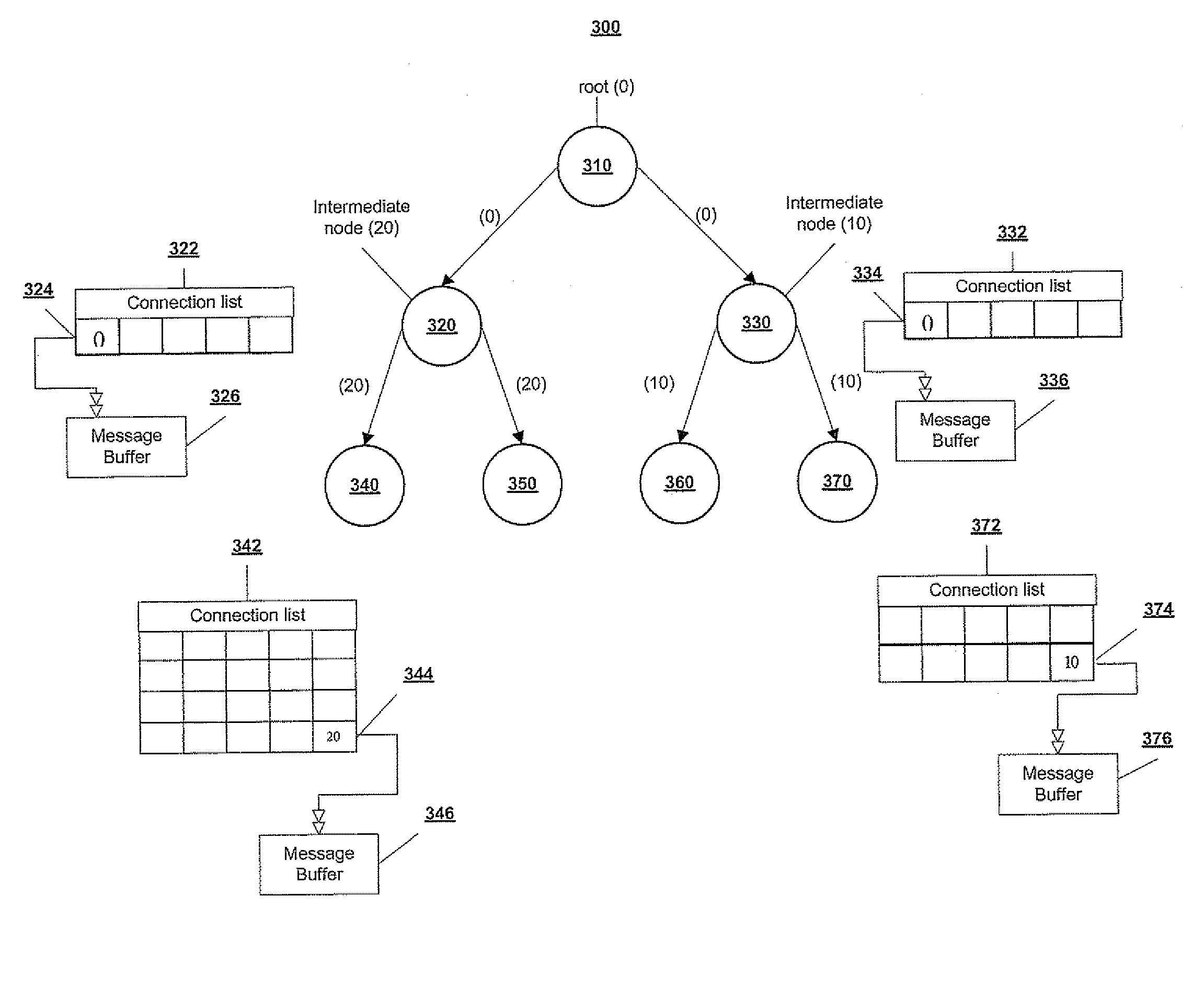
Disclosed is a mechanism on receiving processors in a parallel computing system for providing order to data packets received from a broadcast call and to distinguish data packets received at nodes from several incoming asynchronous broadcast messages where header space is limited. In the present invention, processors at lower leafs of a tree do not need to obtain a broadcast message by directly accessing the data in a root processor's buffer. Instead, each subsequent intermediate node's rank id information is squeezed into the software header of packet headers. In turn, the entire broadcast message is not transferred from the root processor to each processor in a communicator but instead is replicated on several intermediate nodes which then replicated the message to nodes in lower leafs. Hence, the intermediate compute nodes become “virtual root compute nodes” for the purpose of replicating the broadcast message to lower levels of a tree.

Description

CROSS-REFERENCE TO RELATED APPLICATIONS[0001]The present invention is related to the following commonly-owned, co-pending U.S. patent applications filed on even date herewith, the entire contents and disclosure of each of which is expressly incorporated by reference herein as if fully set forth herein. U.S. patent application Ser. No. (YOR920070268US1(21189)), for “A SHARED PERFORMANCE MONITOR IN A MULTIPROCESSOR SYSTEM”; U.S. patent application Ser. No. (YOR920070293US1 (21233)), for “OPTIMIZED COLLECTIVES USING A DMA ON A PARALLEL COMPUTER”; U.S. patent application Ser. No. (YOR920070295US1 (21232)), for “DMA SHARED BYTE COUNTERS IN A PARALLEL COMPUTER”; U.S. patent application Ser. No. (YOR920070297US1 (21208)), for “MULTIPLE NODE REMOTE MESSAGING”; U.S. patent application Ser. No. (YOR920070298US1 (21209)), for “A METHOD AND APPARATUS OF PREFETCHING STREAMS OF VARYING PREFETCH DEPTH”; U.S. patent application Ser. No. (YOR920070299US1 (21212)), for “PROGRAMMABLE PARTITIONING FOR ...

Claims


Application Information

Patent Timeline
IPC IPC(8): H04L12/56
CPCH04L12/1854
Inventor KUMAR, SAMEER
Owner IBM CORP
Learn More