Motion-Validating Remote Monitoring System

a remote monitoring and motion validation technology, applied in the field of remote monitoring and security systems, can solve the problems of high cost of manning such systems, increase the response time, and rely on human supervision

Active Publication Date: 2009-01-08
PIVOTAL VISION
View PDF21 Cites 72 Cited by
  • Summary
  • Abstract
  • Description
  • Claims
  • Application Information

AI Technical Summary

Benefits of technology

[0009]In one embodiment, the present invention is a method of autonomously monitoring a remote site, including the steps of locating a primary detector at a site to be monitored; creating one or more geospatial maps of the site using an overhead image of the site; calibrating the primary detector to the geospatial map using a detector-specific model; detecting an object in motion at the site; tracking the moving object on the geospatial map; and alerting a user to the presence of motion at the site.
[0010]In another embodiment, the present invention is a motion-validating monitoring system that includes

Problems solved by technology

One of the drawbacks to such traditional monitoring systems is that they often rely on human supervision to view video images, interpret the images, and determine a relevant course of action such as alerting authorities.
The high cost of manning such systems makes them impractical when a large number of remote sites require monitoring

Method used


Image

  • Motion-Validating Remote Monitoring System
  • Motion-Validating Remote Monitoring System
  • Motion-Validating Remote Monitoring System

Examples


Embodiment Construction

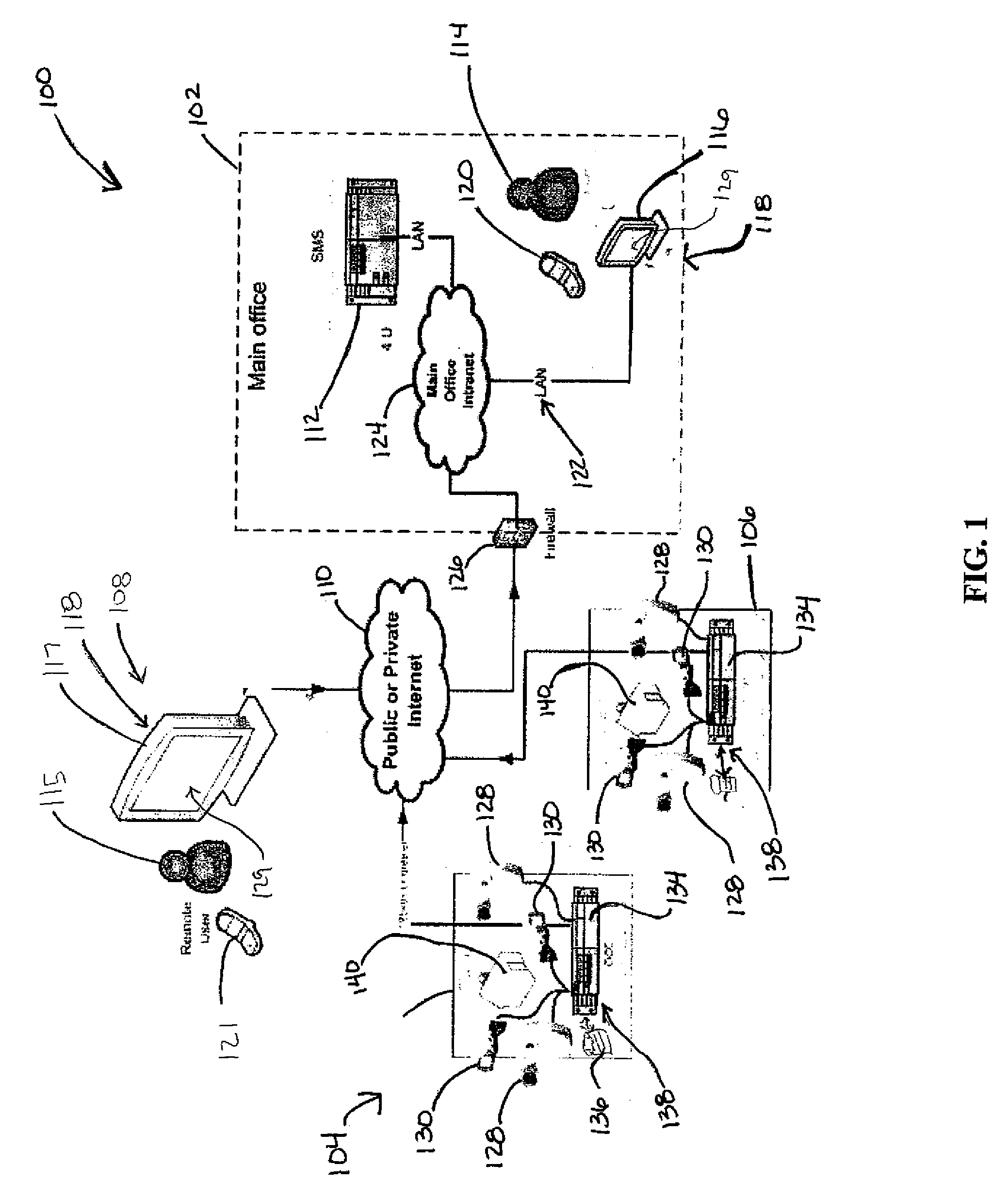
[0061]Referring to FIG. 1, in one embodiment, the present invention is a motion validating monitoring system 100 that includes a main office 102, a first remote site 104, an optional second remote site 106, a remote user location 108, and Internet 110. System 100 may include additional remote sites depending on the number of locations requiring remote monitoring. Main office 102 connects to remote sites 104 and 106, and with remote user location 108 via Internet 110.

[0062]In one embodiment, main office 102 includes a ScadaCam Management Server (SMS) 112, internal office user 114, computer terminal 116 with multi-detector viewer (MCV) software 118, wireless communication device 120, local area network (LAN) 122, main office intranet 124, and firewall 126. Wireless communication device 120 may be a mobile telephone, pager, or other wireless handheld communication device. Computer terminal 116 connects to SMS 112 via main office intranet 124 and LAN 122. In other embodiments of main of...


PUM


Abstract

A method of autonomously monitoring a remote site, including the steps of locating a primary detector at a site to be monitored; creating one or more geospatial maps of the site using an overhead image of the site; calibrating the primary detector to the geospatial map using a detector-specific model; detecting an object in motion at the site; tracking the moving object on the geospatial map; and alerting a user to the presence of motion at the site. In addition thermal image data from a infrared cameras, rather than optical/visual image data, is used to create detector-specific models and geospatial maps in substantially the same way that optical cameras and optical image data would be used.

Description

RELATED APPLICATION [0001]The present application claims priority to U.S. Provisional Application No. 60 / 958,192, filed Jul. 3, 2007, and entitled MOTION-VALIDATING REMOTE MONITORING SYSTEM, which is incorporated by reference herein in its entirety.FIELD OF THE INVENTION [0002]The invention relates generally to remote monitoring and security systems. More specifically, the invention relates to motion-validating remote monitoring systems and methods.BACKGROUND OF THE INVENTION [0003]Standard closed-circuit television (CCTV) systems have long been used to monitor locations requiring security. Such CCTV systems remotely monitor buildings, military installations, infrastructure, industrial processes, and other sensitive locations. As real and perceived threats against persons and property grow, the list of locations requiring remote security monitoring also grows. For example, regularly unmanned infrastructure such as power substations, oil rigs, bridges, and so on, may now require prot...

Claims


Application Information

Patent Timeline
IPC IPC(8): G06K9/62G06V10/24
CPCG06K9/00771G08B13/19608G08B13/194G06K9/32G06T2207/30232G06T7/292G06V20/52G06V10/24G06T17/05G08B13/1963H04N5/144G06T7/20G08B13/19602G08B13/19641G08B13/1961G08B13/19645G06T7/70G08B13/19604
Inventor GORNICK, JOHN R.MOKSNES, CRAIG B.
Owner PIVOTAL VISION
Why Eureka
Try Eureka