Rail clamp

a clamping and rail technology, applied in the surgical field, can solve the problems of inadequate space in the clamping mechanism between the clamping members, and achieve the effect of loose dimensional tolerance and easy navigation

Inactive Publication Date: 2009-01-15
SCOTT CHRISTOPHER P
View PDF9 Cites 24 Cited by
  • Summary
  • Abstract
  • Description
  • Claims
  • Application Information

AI Technical Summary

Benefits of technology

[0007]In various embodiments, the present invention may solve some or all of the needs mentioned above. Typical embodiments of the invention provide a clamp mechanism for a surgical device that allows a user to open...

Problems solved by technology

However, in its second position, the clamp mechanism has i...

Method used


Image

  • Rail clamp
  • Rail clamp
  • Rail clamp

Examples


Embodiment Construction

[0027]The invention summarized above and defined by the enumerated claims may be better understood by referring to the following detailed description, which should be read with the accompanying drawings. This detailed description of particular preferred embodiments of the invention, set out below to enable one to build and use particular implementations of the invention, is not intended to limit the enumerated claims, but rather, it is intended to provide particular examples of them.

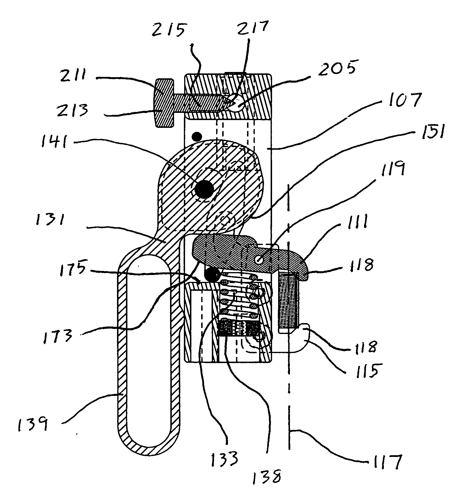
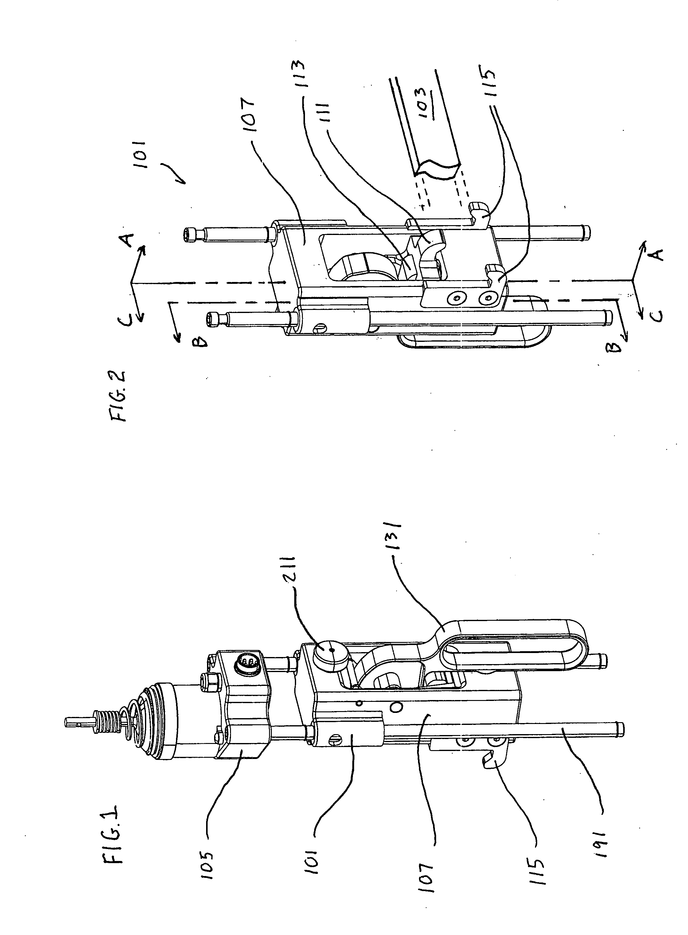
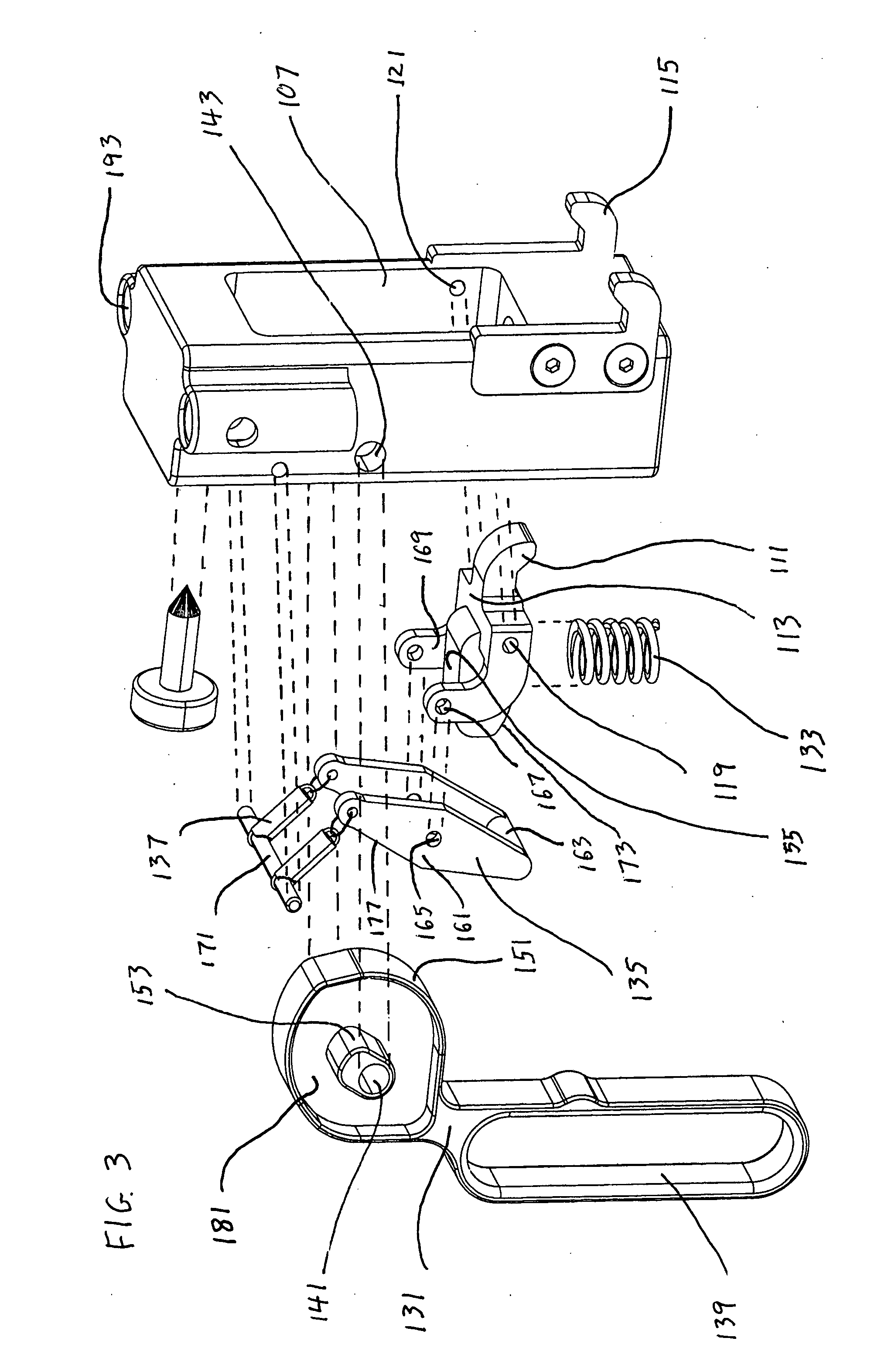
[0028]With reference to FIGS. 1 & 2, the first embodiment of the invention is a rail clamp 101 configured to clamp on a mount structure in the form of a rail 103 of an OR (operating room) table. The rail clamp is configured to carry a base 105 of a surgical device, such as a multi-jointed fixture for holding a retractor. The rail clamp includes an actuation mechanism and a clamp mechanism. The actuation mechanism is configured to actuate the clamp mechanism so as to clamp the housing on to the rail. The ...


PUM


Abstract

A clamp for attaching a medical device to an OR table rail, including two closable clamp jaws that close to an extreme position that leaves inadequate room for the rail. A handle actuates the jaws apart, and a spring biases them together through a range of jaw positions. A lock member is biased to swing through a range of lock positions in which it progressively engages and locks the jaw mechanism through its range of jaw positions. A pair of bars carries the medical device on the clamp, and allows it to be adjustably positioned with respect to the rail.

Description

[0001]The present invention relates generally to a support apparatus for a medical device, and more particularly, to a manually operated rail clamp for attaching a surgical device to a side rail of an operating table.BACKGROUND OF THE INVENTION[0002]A variety of surgical devices, such as instrument positioners, limb positioners, stirrups, and drape screens, are routinely attached to OR (operating room) tables during surgical procedures. To support such surgical devices, OR tables are generally provided with rails on either side of the table, extending along the length of the table. The rails are generally of a common configuration and dimension (e.g., commonly having a rectangular cross-section of 1⅛″ by ⅜″ in the U.S.), but are not typically manufactured and maintained with tight dimensional tolerances that are amenable to quick-attachment mechanisms.[0003]Typically, each surgical device is provided with a rail clamp configured to clamp on to the OR table rail at a position determi...

Claims


Application Information

Patent Timeline
IPC IPC(8): B25B5/00
CPCA61G13/101F16B2/10Y10T24/44684Y10T24/44402Y10T403/7105F16B2/185
Inventor SCOTT, CHRISTOPHER P.CAHAYLA, JASON R.MODES, RICHARD A.GRIECCI, JOHN A.
Owner SCOTT CHRISTOPHER P
Why Eureka
Try Eureka